Apparatus and process for dicing a deformable product

a technology a process, which is applied in the field of cubing or dicing a deformable product apparatus and a method, can solve the problems of requiring frequent maintenance, laborious operation, and prone to harp wire breakage, so as to prevent the build-up of products and minimize the wear of the chopping assembly components. , the appearance is squar

Active Publication Date: 2005-01-13
LEPRINO FOODS
View PDF30 Cites 31 Cited by
  • Summary
  • Abstract
  • Description
  • Claims
  • Application Information

AI Technical Summary

Benefits of technology

[0008] The V-cuber can advantageously be mounted directly upstream of a dicer / shredder (such as a vertical feed shredder (VFS) as disclosed in pending U.S. patent application Ser. No. 09 / 790,515, or an Urschel7 model RAD, CC, RAA, or RA dicer) in a manufacturing line. By arranging the manufacturing line in this manner, the V-cuber can be completely automated, requiring minimal labor to operate and monitor. Therefore, a single operator can operate in excess of eight V-cuber machines at one time. This is a marked improvement over conventional harp style machines, which could require as many as two operators per machine. Also, since the V-cuber is automatic, the risk of injury due to operation of the device is substantially reduced. With this automatic arrangement, when processing stacked slabs of mozzarella cheese, production rates of 16,000-24,000 lbs / hr at 3″ cubes, and 9,000-10,000 lbs / hr at 1″ cubes, are readily attainable from a single V-cuber machine. This equates to an increase of 80-150% more product than a conventional harp style machine, thereby increasing maximum throughput and / or reducing the number of machines required to handle a given production rate.
[0029] To accomplish the elliptical motion, the elongated blade of the chopping assembly is preferably fixedly supported at each end by a drive rod. Preferably, each drive rod is coupled at its lower end to an eccentric drive wheel, while the upper ends of the drive rods are slidably received in pivotable T-shaped rod supports, which are fixed against translation relative to the conveyor assembly. The eccentric drive wheels preferably each include a center shaft, about which the drive wheels are driven for rotation by a chopper drive motor, and an offset shaft, to which the drive rods are coupled. The chopper drive motor is preferably variable frequency electric drive motor, but other suitable drive means, such as hydraulic drive, chain drive, and the like, may also be used. When the eccentric drive wheels are driven for rotation about their central shafts by the chopper drive motor, the offset shafts, and hence the lower ends of the drive arms, move in a circular motion. The upper ends of the drive rods are allowed to pivot and slide relative to the T-shaped rod supports, but the supports are fixed against translation. Since the T-shaped supports are positioned above the midpoint of the drive rods, the elongated blade will move a greater distance in the vertical direction than in the feed direction. The foregoing is but one preferred arrangement that generates the preferred elliptical motion of the elongated blade of the chopping assembly. Of course there are numerous working parameters that can be adjusted to vary the motion of the elongated blade, such as, e.g., the vertical component of motion, the horizontal component of motion, the cutting depth, the cycle speed, the maximum vertical displacement, the maximum horizontal displacement, and the like. It should be apparent that the chopping assembly components, as well as the rest of the V-cuber machine, could be scaled-up in order to produce larger blocks of product and / or to handle larger and / or harder products. Moreover, the dynamic characteristics of the chopping assembly can be correspondingly adjusted to effectively cut such products.

Problems solved by technology

Harp style cutters, however, are prone to breakage of the harp wires, are labor intensive to operate, and require frequent maintenance.
Moreover, these harp style cutters cannot satisfactorily cut soft or high moisture products, such as, for example, mozzarella cheese, while providing uniform, smooth profile cut blocks of the cheese.
This arrangement is problematic for several reasons.
First, as the product is being cut, each slicer blade displaces a small amount of the product.
Since the product is simultaneously sliced by all of the slicer blades, the amount of product displaced by all of the slicer blades is significant.
This compaction of the product increases the force required to feed the product through the slicers and may exacerbate the adherence of the product to the slicer blades.
A second problem with this type of ganged cutter is that when the product comes into contact with all the slicers simultaneously, the product will encounter substantial resistance to conveyance.
Thus, a substantial force will be applied to the shaft on which the slicers are mounted, which has a propensity to smear the product, and may plug and / or damage the dicing machine.
As a result of these two problems, soft and / or tacky products may not be properly conveyed through the ganged cutting assembly.
One disadvantage of this arrangement is that, as the product reaches the trailing (upward rotating) edge of the slicer blades, the product will be biased in the upward direction by the upward motion of the trailing edge of the slicer blades.
Thus, some tacky and / or soft products will not be effectively stabilized and may tend to ride-up on the slicer blades, where they will no longer be conveyed properly.
Furthermore, because the slicer blades are spaced at such a great distance apart in the feed direction, the overall length of the slicing machine is correspondingly great.
The large size of this configuration makes it difficult or impossible to effectively mount the machine above or upstream of another machine in an assembly line.

Method used


Image

  • Apparatus and process for dicing a deformable product
  • Apparatus and process for dicing a deformable product
  • Apparatus and process for dicing a deformable product

Examples


Embodiment Construction

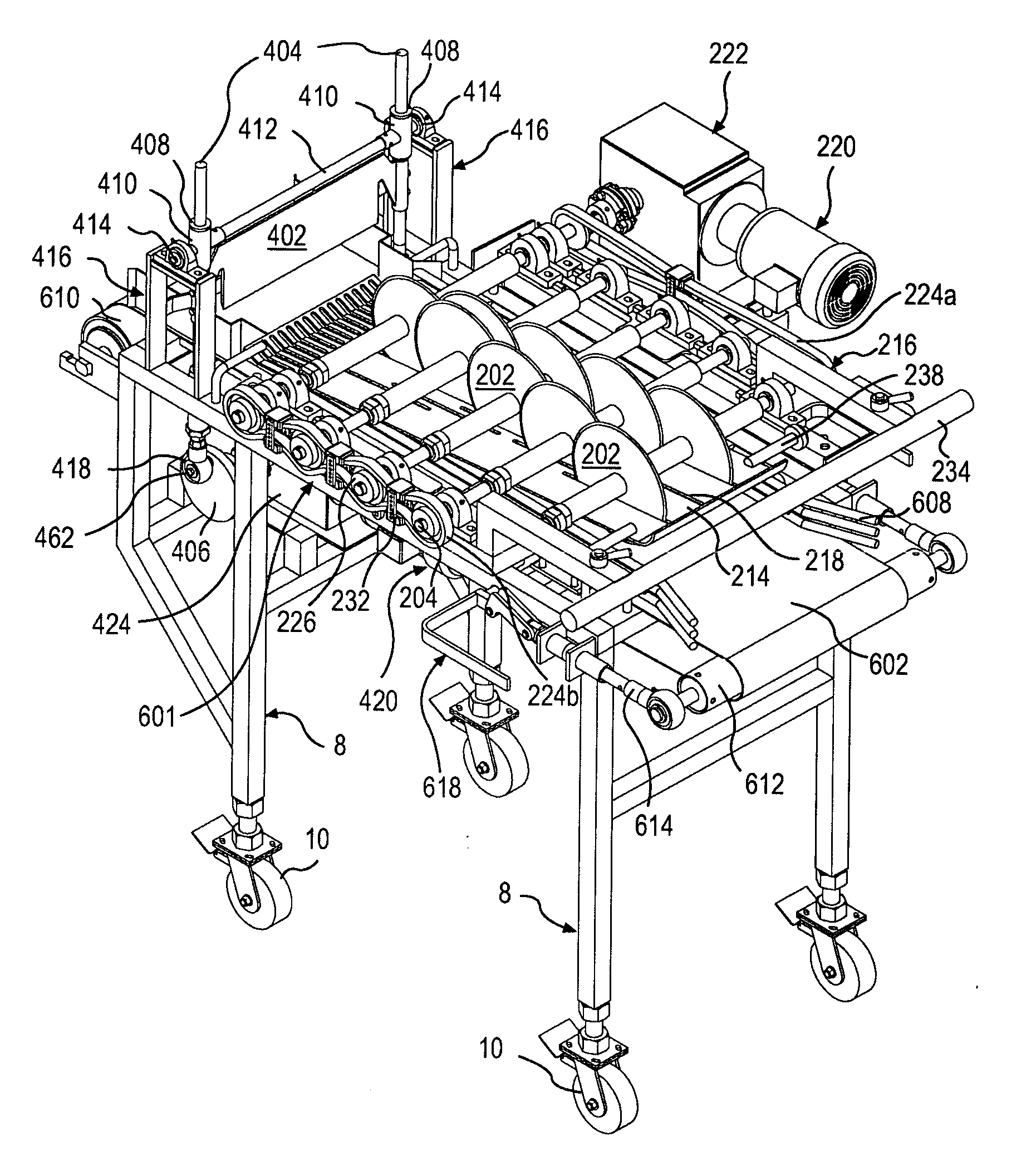
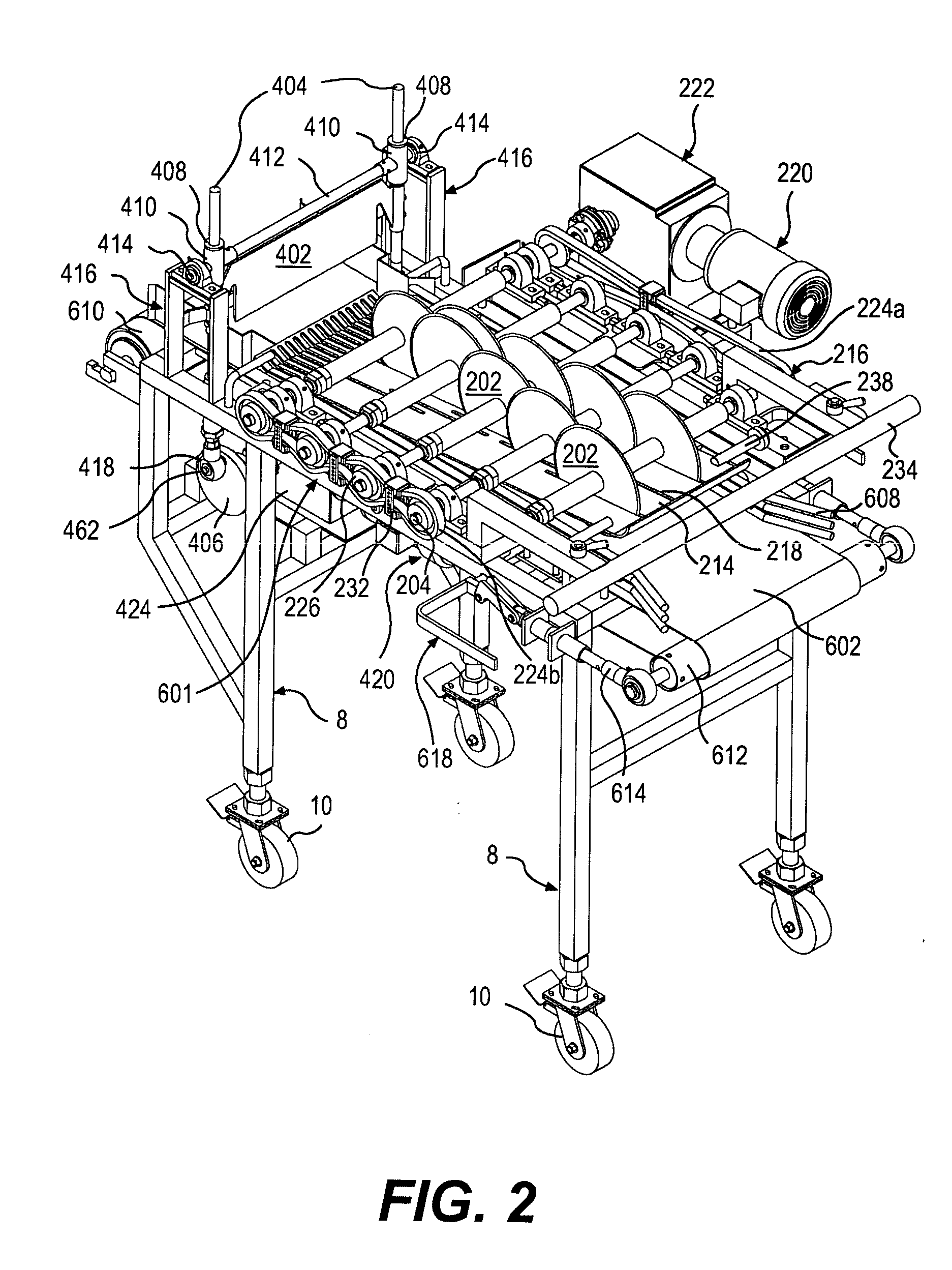
[0039] Our invention generally relates to an apparatus and method for dicing a deformable product to form blocks or cubes of the product. For illustrative purposes, the preferred embodiment of our invention is described in connection with the production of cheese, and in particular mozzarella style cheese. The apparatuses and methods of our invention are not limited to the production of cheese, however, and can be used in the production or processing of any number of products, as discussed above.

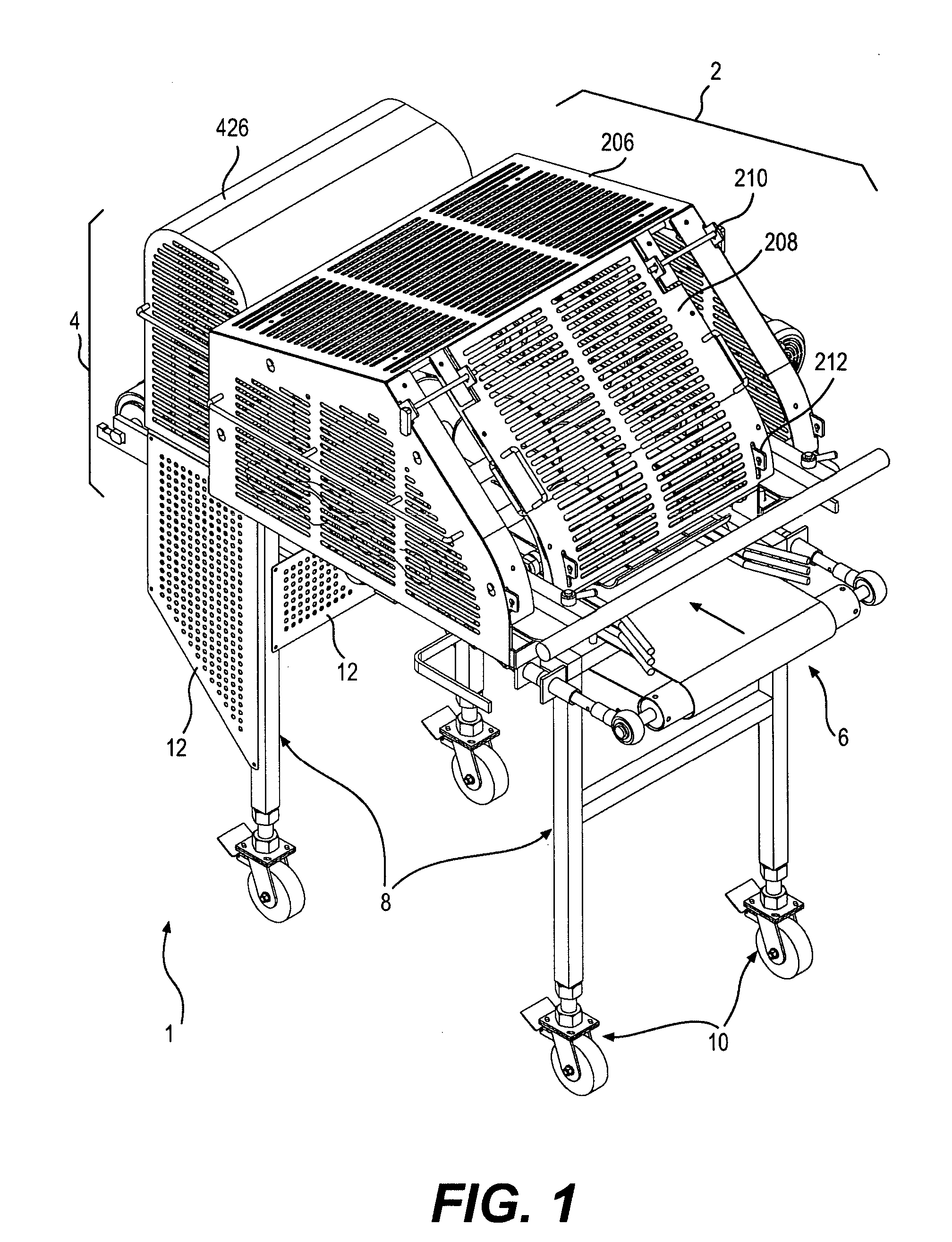
[0040] Our preferred embodiment of the V-cuber 1 is configured to cut mozzarella cheese into blocks for feeding to a shredding device, such as a VFS shredder. The blocks of cheese produced should be in the range of 1″-3″ wide, 1″-3″ long, and 1″-4.5″ thick, depending on the size and type of shredder that the blocks will be fed to. As shown in FIG. 1, the V-cuber 1 comprises a conveyor assembly 6 that conveys the cheese in a feed direction, a slitter assembly 2 having a plurality of circular...


PUM

PropertyMeasurementUnit
speedaaaaaaaaaa
speedaaaaaaaaaa
diameteraaaaaaaaaa

Abstract

An apparatus for cutting a product includes a conveyor assembly and a slitter assembly. The conveyor assembly conveys the product in a feed direction and defines a conveyance surface, on which the product is conveyed. The slitter assembly slits the product into strips as the product is conveyed in the feed direction. The slitter assembly comprises a plurality of cutting elements arranged in a V shape and overlapping one another in the feed direction, as viewed in a direction substantially normal to the conveyance surface. A chopping assembly is positioned downstream of the slitter assembly. The chopping assembly comprises an elongated blade, which moves in an elliptical cutting motion, such that it has a component in the downward direction to sever the strips of product, and a component in the feed direction to toss the severed pieces of product in the feed direction.

Description

FIELD OF THE INVENTION [0001] Our invention generally relates to an apparatus and method for cubing or dicing a deformable product to form blocks or cubes of the product. BACKGROUND OF THE INVENTION [0002] To date, various different machines have been used for cubing or dicing deformable products. One common type of machine used for cubing or dicing a deformable product is a harp style cutter. The harp style cutter is most commonly used to cut moderately deformable products, such as cheese, meats, bakery products, potato products, and the like. Harp style cutters use a plurality of wires or wire blades stretched taught within a rigid harp frame to cut the deformable product into individual pieces. Generally, either hydraulic or pneumatic cylinders are used to force the harp frame over a slab or loaf of deformable product, thereby severing the slab or loaf into a plurality of slices, blocks, or cubes. Harp style cutters, however, are prone to breakage of the harp wires, are labor int...

Claims


Application Information

Patent Timeline
Patent Type & Authority Applications(United States)
IPC IPC(8): B26D3/20B26D3/22B26D7/06B26D9/00
CPCB26D3/20B26D9/00B26D7/0625B26D3/22Y10T83/6587Y10T83/7876Y10T83/04Y10T83/6491Y10T83/773Y10T83/6483Y10T83/6478
Inventor AKINS, KEVIN BRADLEYBOBKOWSKI, THEODORE ALANKIELSMEIER, LESTER O.OLIVEIRA, PAUL JOSEPHPREWITT, WILLIAM CHARLESVOLK, JAMES MICHAEL
Owner LEPRINO FOODS
Why Eureka
Try Eureka