Multi-wavelength generating method and apparatus based on flattening of optical spectrum

a multi-wavelength and optical spectrum technology, applied in the field of optical communication technologies, can solve the problems of inability to dynamically control the deviation of power level among longitudinal modes, incoherent and thus unsuitable for dense wdm transmissions involving a large number of wavelengths, and inability to coherently and thus unsuitable for dense wdm transmissions

Inactive Publication Date: 2005-01-13
NIPPON TELEGRAPH & TELEPHONE CORP
View PDF6 Cites 9 Cited by
  • Summary
  • Abstract
  • Description
  • Claims
  • Application Information

AI Technical Summary

Benefits of technology

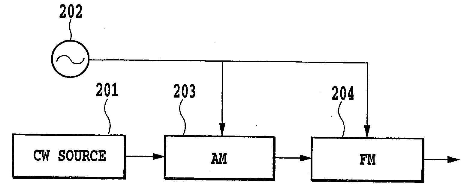
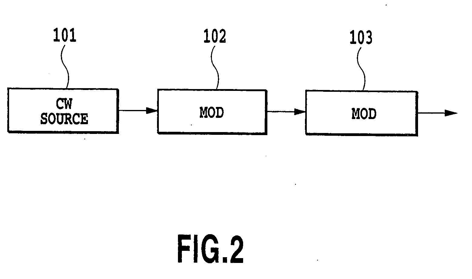
A method according to the present invention comprises a first process of obtaining a discrete spectrum of a mode spacing Δf using an output light obtained by modulating the amplitude or phase of a CW output from a single-wavelength light source or an output light from a pulsed light source or an optical-pulse output circuit for outputting a pulsed light of a repetition frequency Δf, and a second process of modulating the discrete spectrum of the mode spacing Δf at a frequency Ω<2 fm when the discrete spectrum has a band 2 fm, thereby making it possible to dynamically control power level deviations among the longitudinal modes of the discrete spectrum.

Problems solved by technology

A light obtained by slicing a spectrum of the ASE light, however, is incoherent and thus unsuitable for dense WDM transmissions involving a large number of wavelengths.
Such design and production, however, is in effect difficult.
Further, since the shape of the optical spectrum is uniquely determined by its design parameters, it is impossible to dynamically control power level deviations among the longitudinal modes.
Moreover, the process of flattening an optical spectrum using the optical filter with the reverse transmission characteristic also has problems in design difficulty and uniquely decided output spectrum as in the above described supercontinuum generation.

Method used


Image

  • Multi-wavelength generating method and apparatus based on flattening of optical spectrum
  • Multi-wavelength generating method and apparatus based on flattening of optical spectrum
  • Multi-wavelength generating method and apparatus based on flattening of optical spectrum

Examples


third embodiment

[Third Embodiment of the Multi-wavelength Generating Apparatus]

FIG. 34 shows the configuration of the third embodiment of the multi-wavelength generating apparatus according to the present invention.

As shown in FIG. 34, the multi-wavelength generating apparatus of this embodiment is composed of the light source 1 generating a light having a single central wavelength, a bipolar Mach-Zehnder intensity modulator 20, a oscillator 3 for generating a signal voltage repeated with a predetermined period, the power regulator 4, the power-varying DC power supply 5, and a phase adjuster 6. The power regulator 4 and the phase regulator 6 are coupled together in series.

The bipolar Mach-Zehnder intensity modulator 20 has such a well-known configuration that an incident light is branched into two optical paths so that output lights from the optical modulators arranged in the corresponding optical paths are multiplexed and converged for emission. Each of the branched paths has optical modulatin...

fourth embodiment

[Fourth Embodiment of the Multi-wavelength Generating Apparatus]

FIG. 35 shows the configuration of the fourth embodiment of the multi-wavelength generating apparatus according to the present invention.

The multi-wavelength generating apparatus of this embodiment shown in FIG. 35 comprises, instead of the oscillator 3 of the third embodiment, an oscillator 3a for generating a sinusoidal signal voltage as one for generating a signal voltage repeated with a predetermined period. It further comprises a multiplier 7 coupled to the power regulator 4 in series.

This configuration varies the frequency of the signal voltage applied to the opposite electrodes of the Mach-Zehnder intensity modulator 20. That is, an output signal voltage from the oscillator 3a is applied to one of the electrodes after having its frequency multiplied by the multiplier 7, while the output frequency from the oscillator 3a is applied to the other electrode as it is.

In this embodiment, the signal voltage repeate...

fifth embodiment

[Fifth Embodiment of the Multi-wavelength Generating Apparatus]

FIG. 36 shows the configuration of the fifth embodiment of the multi-wavelength generating apparatus according to the present invention.

The multi-wavelength generating apparatus of this embodiment shown in FIG. 36 is composed of the light source 1 generating a light having a single central wavelength, a group of optical modulators 2c consisting of the bipolar Mach-Zehnder intensity modulator 20 and a phase adjuster 28 coupled together in series, the oscillator 3 for generating a signal voltage repeated with a predetermined period, the power regulator 4, the power-varying DC power supply 5, and the phase regulator 6.

A signal voltage from the oscillator 3 has its power regulated properly by the power regulator 4 and is then applied to the Mach-Zehnder intensity modulator 20. This signal voltage further has its temporal position regulated by the phase regulator 6, has its power regulated properly by the power regulator ...


PUM

PropertyMeasurementUnit
optical-aaaaaaaaaa
phaseaaaaaaaaaa
repetition frequencyaaaaaaaaaa

Abstract

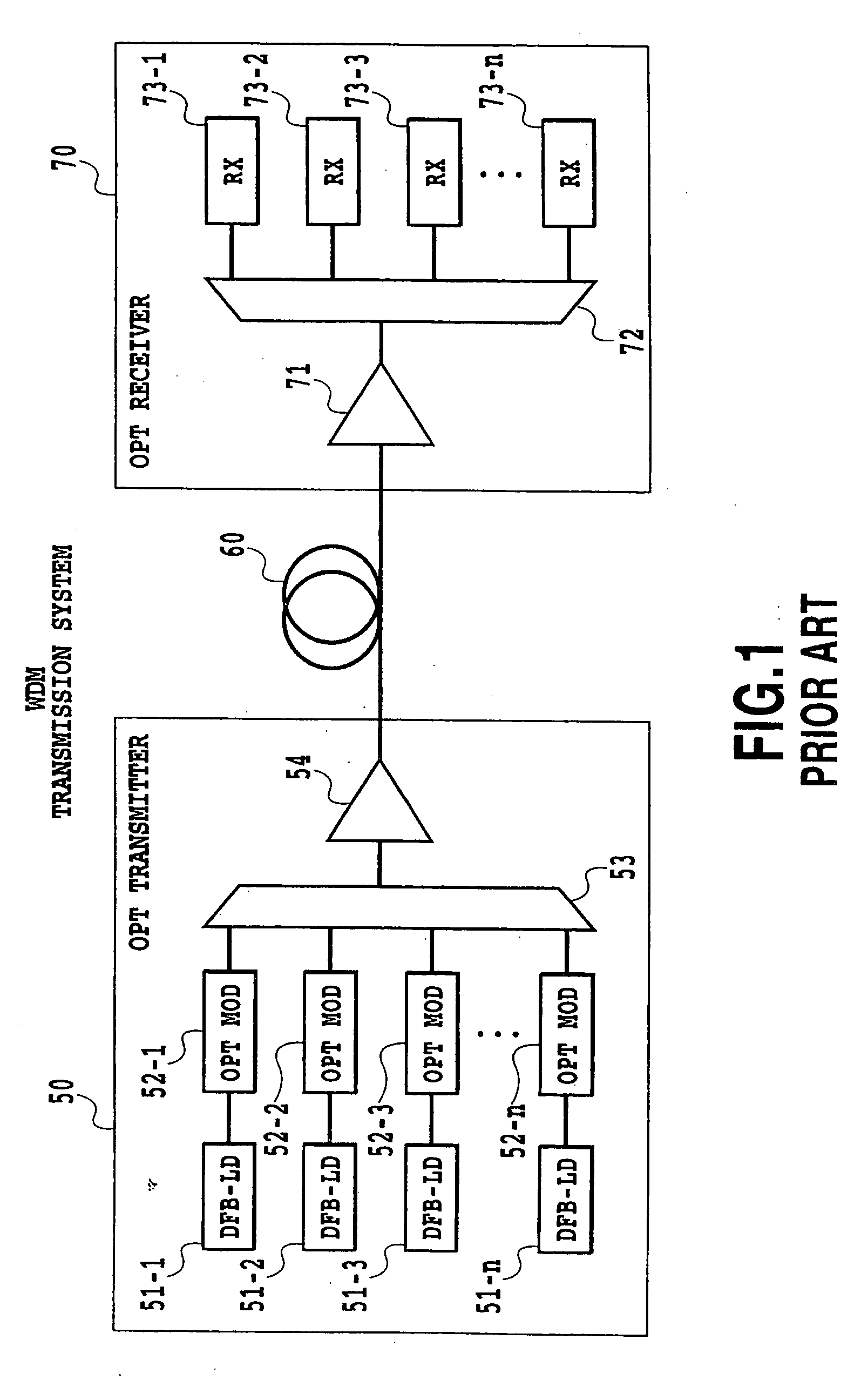
With respect to the relative intensity noise (RIN) for inputs to an optical modulator or the signal-to-noise ratio (SNR) for outputs therefrom, the optical modulator modulating coherent lights of different wavelengths obtained by slicing a spectrum of the multi-wavelength light, the shape of a spectrum of a multi-wavelength light is controlled so that predetermined RIN and SNR can be obtained in accordance with transmission system parameters (the type and distance of optical fibers, the number of repeaters), thus enabling design meeting a performance specification for a conventional transmission section using semiconductor lasers.

Description

This application is based on Japanese Patent Application Nos. 2000-207475 and 2000-207494 both filed Jul. 7, 2000, 2000-218424 filed Jul. 19, 2000 and 2000-266125 filed Sep. 1, 2000, the content of which is incorporated hereinto by reference. BACKGROUND OF THE INVENTION 1. Field of the Invention The present invention relates to a collective multi-wavelength generating technique for use in the field of optical communication technologies, and in particular, to elimination of power level deviations among the modes of a discrete optical spectrum, collective generation of a multi-wavelength light with a plurality of central wavelengths from a light with a single central wavelength, controlling an optical spectrum shape, while slicing a spectrum of coherent multi-wavelength output from a multi-wavelength light source and modulating the coherent multi-wavelength from the multi-wavelength light source with a plurality of optical modulators, output from the multi-wavelength light source s...

Claims


Application Information

Patent Timeline
Patent Type & Authority Applications(United States)
IPC IPC(8): G02F1/01H04B10/155H04B10/18H04J14/02
CPCG02F1/0121H04B10/505H04B10/5051H04B10/50572H04B10/50577H04J14/0221H04B10/50595H04B10/50597H04B10/506H04B10/508H04B10/564H04B10/50593
Inventor FUJIWARA, MASAMICHIARAYA, KATSUHIROTESHIMA, MITSUHIROKANI, JUNICHISUZUKI, KENICHI
Owner NIPPON TELEGRAPH & TELEPHONE CORP
Why Eureka
Try Eureka