Integrated bridge turbine blade

Inactive Publication Date: 2005-01-13
GENERAL ELECTRIC CO
View PDF14 Cites 24 Cited by
  • Summary
  • Abstract
  • Description
  • Claims
  • Application Information

AI Technical Summary

Benefits of technology

[0008] Accordingly, it is desired to provide an improved turbine rotor blade cooling configura

Problems solved by technology

The presently known cooling configurations for first stage turbine blades presently limit the maximum allowed turbine inlet temperature for obtaining a suitable useful life of the blades.
The compl

Method used


Image

  • Integrated bridge turbine blade
  • Integrated bridge turbine blade
  • Integrated bridge turbine blade

Examples


Embodiment Construction

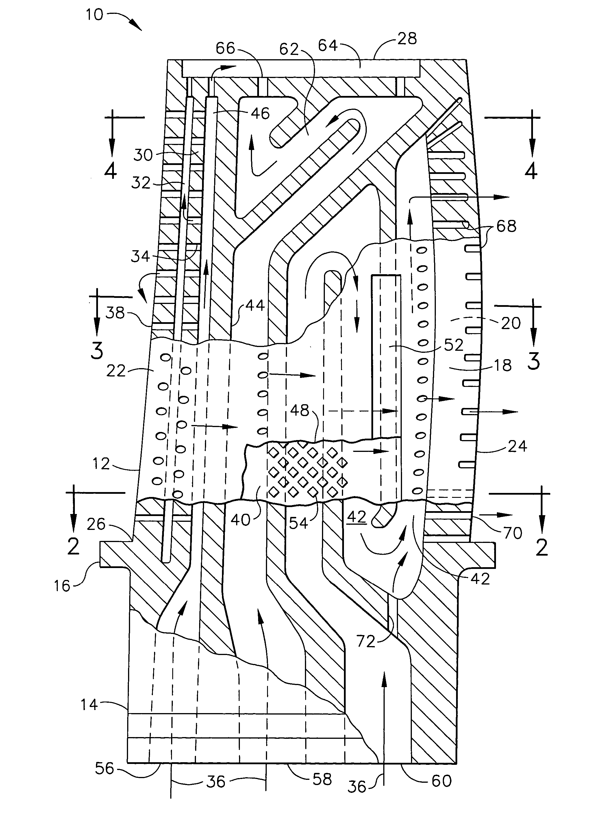
[0016] Illustrated in FIG. 1 is an exemplary first stage turbine rotor blade 10 for use in a gas turbine engine in a high pressure turbine immediately downstream from a combustor thereof. The blade may be used in an aircraft gas turbine engine configuration, or may also be used in non-aircraft derivatives thereof.

[0017] The blade includes a hollow airfoil 12 extending radially in span outwardly from a supporting dovetail 14 joined together at a common platform 16. The dovetail may have any conventional configuration including dovetail lobes or tangs which mount the blade into a corresponding dovetail slot in the perimeter of a turbine rotor disk (not shown). The dovetail is joined to the integral platform by a shank therebetween.

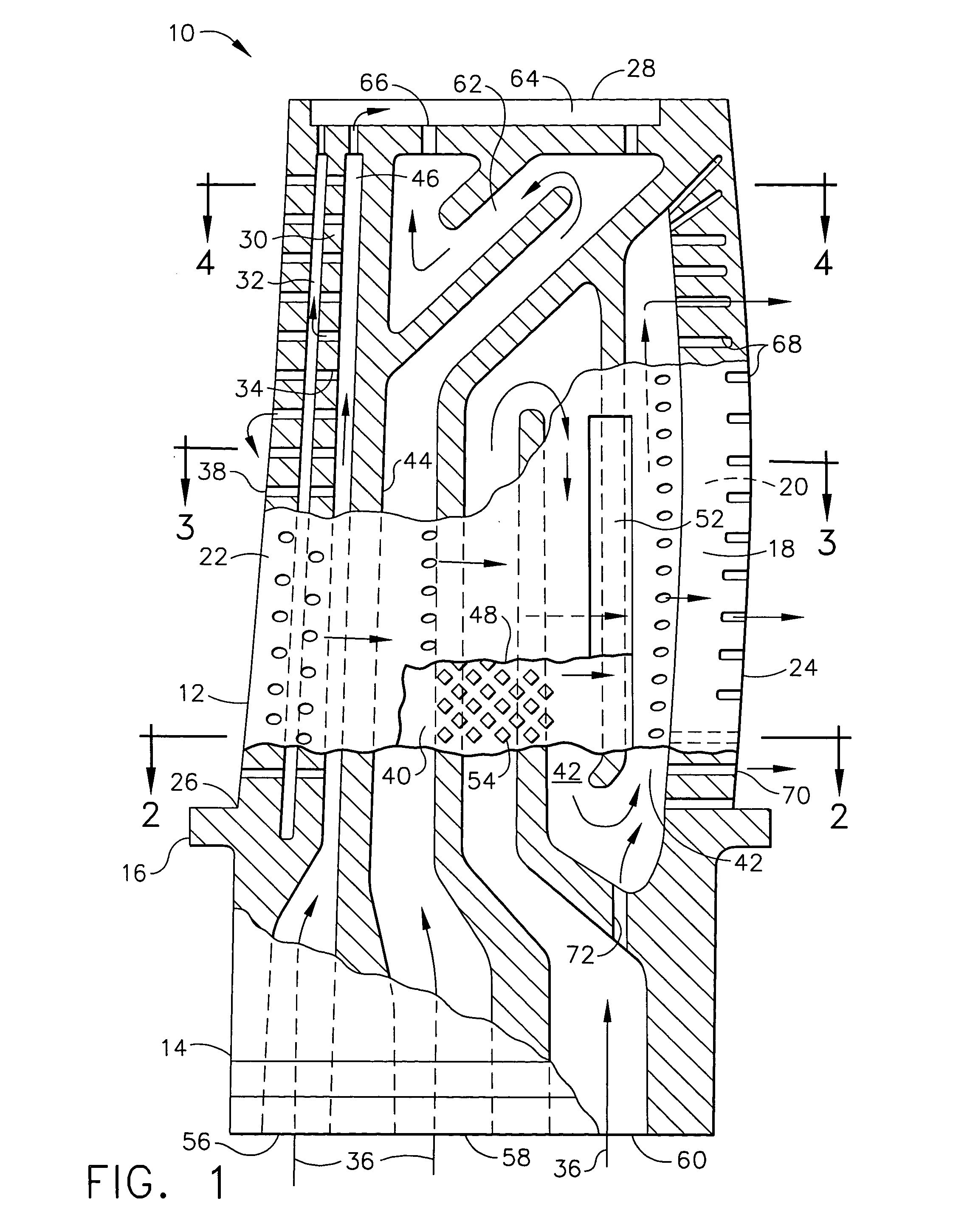
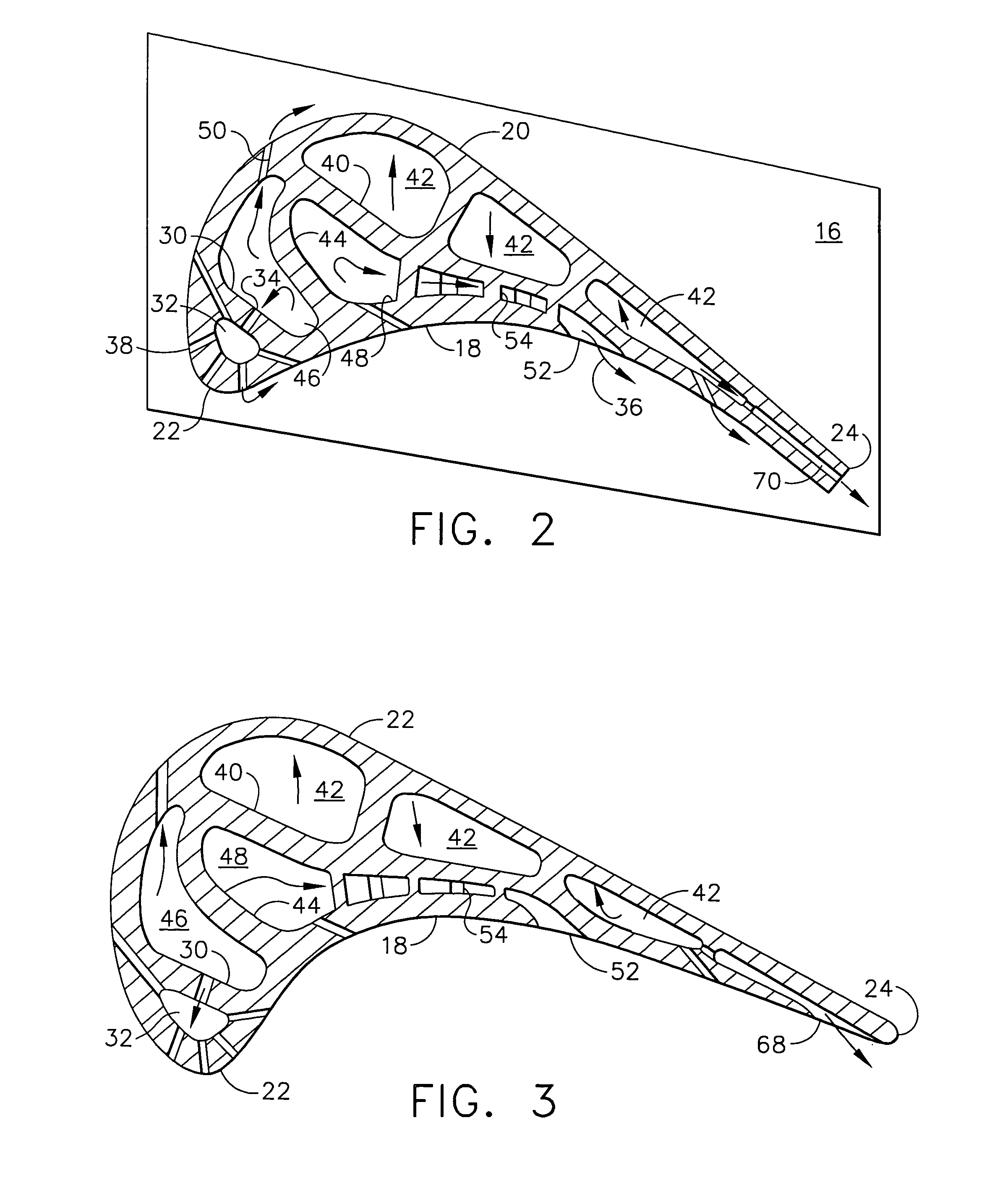
[0018] The airfoil 12 includes a concave pressure sidewall 18 and a laterally or circumferentially opposite convex sidewall 20. The two sidewalls are joined together at axially or chordally opposite leading and trailing edges 22,24, and are spaced apart th...


PUM


Abstract

A turbine blade includes a hollow airfoil integrally joined to a dovetail. The airfoil includes a perforate first bridge defining a flow channel behind the airfoil leading edge. A second bridge is spaced behind the first bridge and extends from a pressure sidewall of the airfoil short of the airfoil trailing edge. A third bridge has opposite ends joined to the pressure sidewall and the second bridge to define with the first bridge a supply channel for the leading edge channel, and defines with the second bridge a louver channel extending aft along the second bridge to its distal end at the pressure sidewall.

Description

[0001] The U.S. Government may have certain rights in this invention pursuant to contract number F33615-02-C-2212 awarded by the U.S. Department of the Air Force.BACKGROUND OF THE INVENTION [0002] The present invention relates generally to gas turbine engines, and, more specifically, to turbine blade cooling therein. [0003] In a gas turbine engine, air is pressurized in a multistage compressor and mixed with fuel for generating hot combustion gases in a combustor. The gases are discharged through a high pressure turbine (HPT) which powers the compressor, typically followed by a low pressure turbine (LPT) which provides output power by typically powering a fan at the upstream end of the engine. This turbofan configuration is used for powering commercial or military aircraft. [0004] Engine performance or efficiency may be increased by increasing the maximum allowed operating temperature of the combustion gases that are discharged to the HPT which extracts energy therefrom. Furthermore...

Claims


Application Information

Patent Timeline
IPC IPC(8): F01D5/18F01D5/20F02C7/18
CPCF01D5/184F01D5/186Y02T50/676Y02T50/673F01D5/20Y02T50/60
Inventor LEE, CHING-PANGHAUBERT, RICHARD CLAYMACLIN, HARVEY MICHAEL
Owner GENERAL ELECTRIC CO
Why Eureka
Try Eureka