Exhaust gas treatment system

a technology of exhaust gas treatment and exhaust gas, which is applied in the direction of separation processes, machines/engines, mechanical equipment, etc., can solve the problems of increasing the cost of treatment, inability to attract and remove dust in sufficient quantities, and not removing all of sulfur trioxide in the exhaust gas by dry electrostatic precipitator

Inactive Publication Date: 2005-01-13
MITSUBISHI HEAVY IND LTD
View PDF3 Cites 27 Cited by
  • Summary
  • Abstract
  • Description
  • Claims
  • Application Information

AI Technical Summary

Benefits of technology

[0011] The present invention has been accomplished to solve the above-described problems. It is the object of the invention to provide an exhaust gas treatment system intended to decrease the costs of treatment and equipment and downsize the system.
[0013] According to this feature, the activated carbon treatment means reliably removes sulfur oxides in the exhaust gas. Thus, it is not necessary to add ammonia to the exhaust gas, thereby converting sulfur trioxide into ammonium sulfate, and to remove the resulting ammonium sulfate by the electrostatic precipitator. Since ammonia for desulfurization treatment is not required, the cost of treatment can be decreased. Moreover, dust in the exhaust gas can be reliably attracted and removed by the electrostatic precipitator. Furthermore, sulfur dioxide and sulfur trioxide in the exhaust gas can be removed by the activated carbon treatment means, thus obviating the need for a wet electrostatic precipitator, and making downsizing and compactness of the system possible.
[0014] In the exhaust gas treatment system, denitration means for treating nitrogen oxides in the exhaust gas may be provided between the electrostatic precipitator and the activated carbon treatment means. Thus, an influx of dust and trace metal elements into the denitration means can be decreased to prevent their deposition on the denitration means, and compactness of the electrostatic precipitator and the denitration means can be achieved.
[0015] In the exhaust gas treatment system, the denitration means may comprise a first denitration catalyst layer, an ammonia decomposing catalyst layer, and a second denitration catalyst layer disposed in a direction of flow, and the denitration means may be an ammonia decomposing denitration catalyst which adds ammonia, in an amount not smaller than an ammonia-reactive amount of the nitrogen oxides in the exhaust gas, to an entrance to the first denitration catalyst layer. Thus, acidic ammonium sulfate, which is formed from sulfur oxides in the exhaust gas and residual ammonia, can be decreased markedly.
[0016] In the exhaust gas treatment system, the electrostatic precipitator may be a high temperature dry electrostatic precipitator for catching the fine particles in the high temperature exhaust gas at 200° C. or higher. Thus, after fine particles of dust contained in the high temperature exhaust gas are removed, denitration and desulfurization are performed. That is, the treatments for removing nitrogen oxides and sulfur oxides in the exhaust gas are performed in a situation where virtually no dust exists in the exhaust gas. Hence, the efficiency of the treatments can be increased.
[0017] In the exhaust gas treatment system, the high temperature exhaust gas may be an exhaust gas discharged from a boiler plant using a fuel having a high sulfur content. Thus, a large amount of sulfur contained in the exhaust gas can be removed reliably.

Problems solved by technology

In recent years, however, emphasis has tended to be placed on environmental problems.
This poses the problem that a large amount of ammonia is required, increasing the cost of treatment.
Moreover, the dry electrostatic precipitator 004 is intrinsically intended to attract dust in the exhaust gas, but since it has to attract a large amount of ammonium sulfate, it may be unable to attract and remove dust sufficiently.
Furthermore, not all of sulfur trioxide in the exhaust gas can be removed by the dry electrostatic precipitator 004.
Thus, the two electrostatic precipitators, 004 and 007, are needed, presenting the problem that the system is upsized and the equipment costs are increased.

Method used


Image

  • Exhaust gas treatment system
  • Exhaust gas treatment system
  • Exhaust gas treatment system

Examples


Embodiment Construction

[0022] An embodiment of the present invention will now be described in detail with reference to the accompanying drawings.

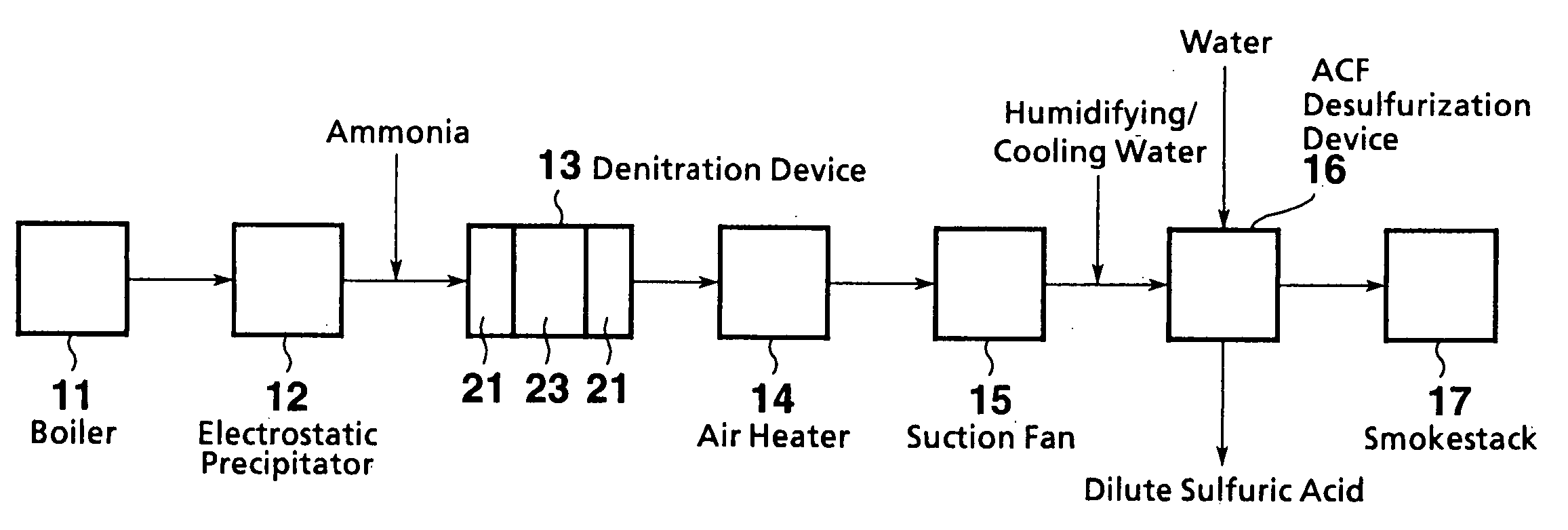
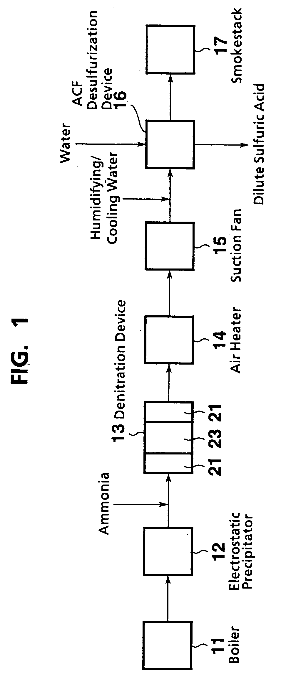
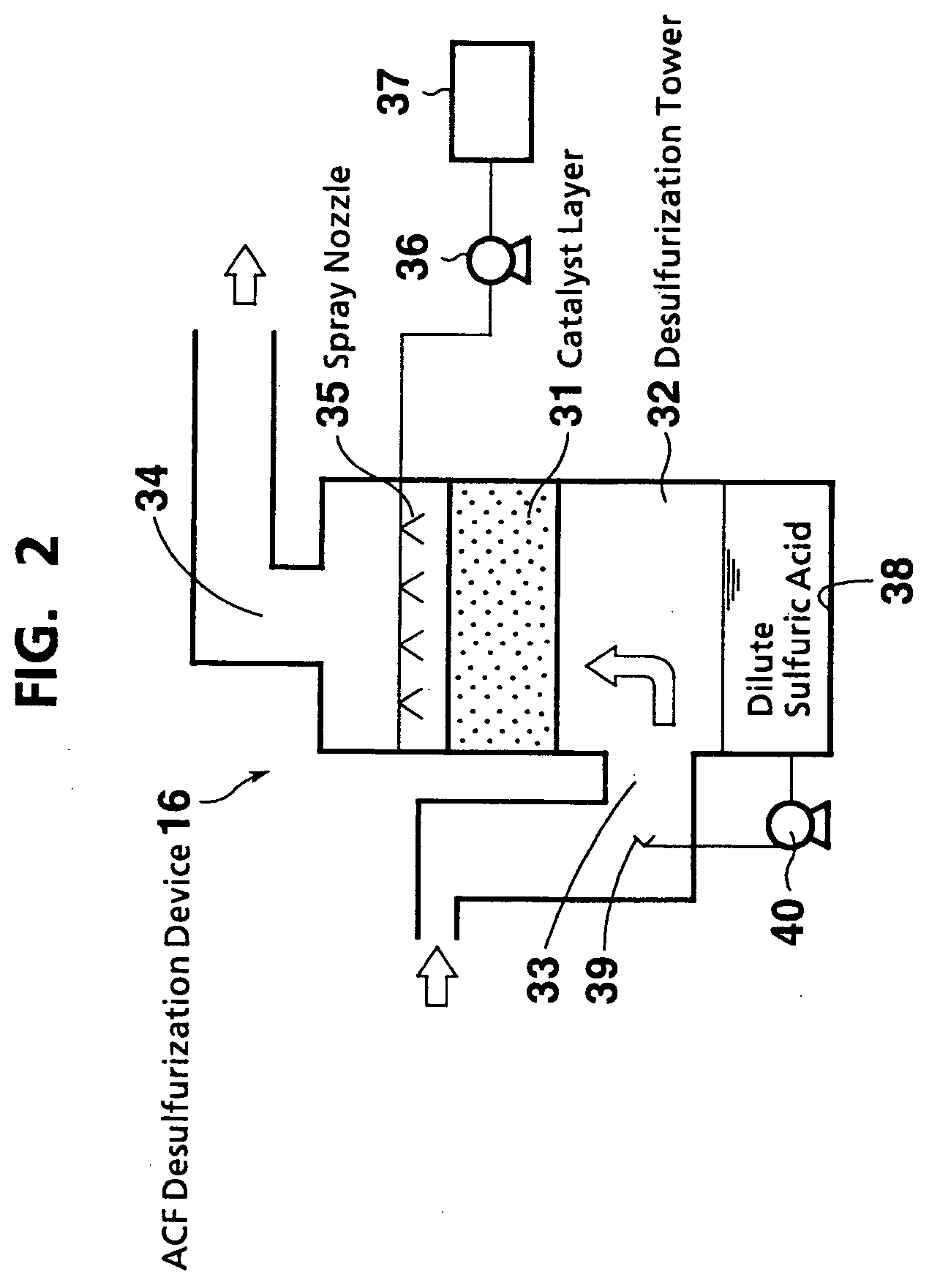
[0023]FIG. 1 schematically shows the configuration of an exhaust gas treatment system according to an embodiment of the present invention. FIG. 2 schematically shows an ACF desulfurization device.

[0024] The exhaust gas treatment system of the present embodiment is used in a boiler plant (baking furnace, incinerator, etc.) which uses a fuel containing high sulfur components such as petroleum coke and Orimulsion.

[0025] As shown in FIG. 1, the exhaust gas treatment system of the present embodiment is composed of a high temperature dry electrostatic precipitator 12, a denitration device 13, an air heater 14, a suction fan 15, an ACF desulfurization device 16, and a smokestack 17 arranged successively with respect to an exhaust gas discharged from a boiler 11.

[0026] The exhaust gas at about 200 to 400° C. is supplied from the boiler 11 to the electrostatic precipi...


PUM

PropertyMeasurementUnit
temperatureaaaaaaaaaa

Abstract

In an exhaust gas treatment system, dust in a high temperature exhaust gas is caught by a high temperature dry electrostatic precipitator, a nitrogen oxide NO2 in the exhaust gas is removed by denitration means, then the exhaust gas is cooled by an air heater, and the exhaust gas is passed through an activated carbon fiber layer of activated carbon treatment means to remove sulfur oxides SO2 and SO3 contained in the exhaust gas. The exhaust gas treatment system reduces the costs of treatment and equipment, and downsizes the system.

Description

[0001] The entire disclosure of Japanese Patent Application No. 2003-192846 filed on Jul. 7, 2003, including specification, claims, drawings and summary, is incorporated herein by reference in its entirety. BACKGROUND OF THE INVENTION [0002] 1. Field of the Invention [0003] This invention relates to an exhaust gas treatment system for purifying a high temperature exhaust gas discharged from a boiler plant or the like which uses a high sulfur content fuel. [0004] 2. Description of the Related Art [0005]FIG. 3 schematically shows the configuration of a conventional exhaust gas treatment system. As shown in FIG. 3, the conventional exhaust gas treatment system is composed of a denitration device 002, an air heater 003, a dry electrostatic precipitator 004, a suction fan 005, a desulfurization device 006, a wet electrostatic precipitator 007, and a smokestack 008 arranged successively with respect to an exhaust gas discharged from a boiler 001. [0006] Thus, the exhaust gas discharged fr...

Claims


Application Information

Patent Timeline
Patent Type & Authority Applications(United States)
IPC IPC(8): B01D53/50B01D53/56B01D53/74B01D53/77B01D53/86
CPCB01D53/8631B01D53/86
Inventor KOBAYASHI, NORIHISAARAKAWA, YOSHIHISAYOKOSHIKI, TATSUOODA, NAOYOSHIONISHI, TOSHIYUKI
Owner MITSUBISHI HEAVY IND LTD
Why Eureka
Try Eureka