
Wet scrubbing apparatus and method for controlling NOx emissions

a technology of nox emissions and wet scrubbing, which is applied in the direction of chemistry apparatus and processes, separation processes, dispersed particle separation, etc., can solve the problems of significant limitations in the sncr process, the limitation of the percentage of nox reduction to about 60% and lower, and the limitation of the scr process

Active Publication Date: 2005-01-13
BELCO TECH
View PDF21 Cites 22 Cited by
  • Summary
  • Abstract
  • Description
  • Claims
  • Application Information

AI Technical Summary

Benefits of technology

[0054] The flue gas may travel through the apparatus at a rate ranging from 3-26 feet/second, the flue gas exit has N

Problems solved by technology

The SNCR process is significantly limited, however, by the fact that it requires a very high operational temperature, ranging from 800°-1200° C. Even at these high operational temperatures, the percentage of NOx reduction is limited to about 60% and lower in most cases.
The process can be carried out at temperatures significantly lower than the SNCR process, such as 250°-600° C. However, the SCR process also has limitations.
The SCR process is more costly than the SNCR process, as the catalyst deteriorates with age and requires replacement every 3-5 years.
Additionally, the catalyst can convert some of the SO2 present in the flue gas to SO3, which may cause additional pollution concerns.
Lastly, in certain applications the catalyst bed may trap particulate matter causing blinding of the catalyst and / or a build-up of flue-gas pressure drop.

Method used


Image

  • Wet scrubbing apparatus and method for controlling NOx emissions
  • Wet scrubbing apparatus and method for controlling NOx emissions
  • Wet scrubbing apparatus and method for controlling NOx emissions

Examples


Embodiment Construction

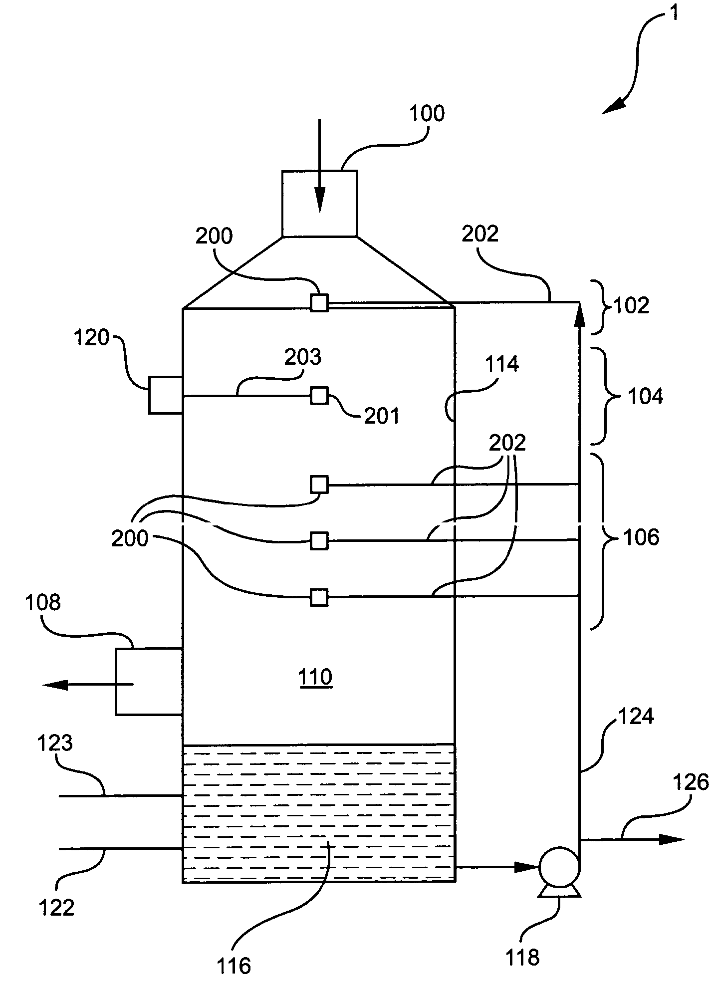
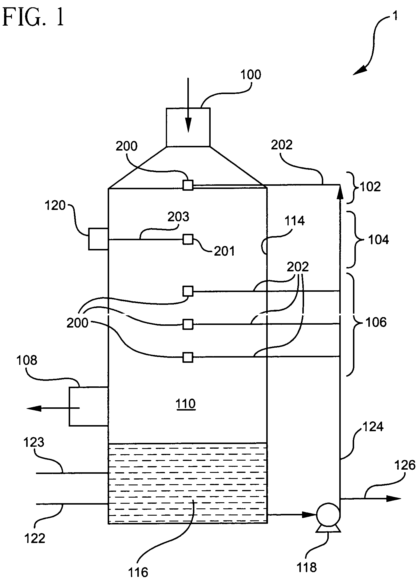
[0065] The present invention is generally directed to a wet scrubbing apparatus, such as the wet scrubber 1 shown in FIG. 1, and a method of reducing NOx emissions using the wet scrubbing apparatus of the present invention. It should be appreciated that the disclosure in U.S. Provisional Application No. 60 / 485,780 is fully incorporated herein by reference.

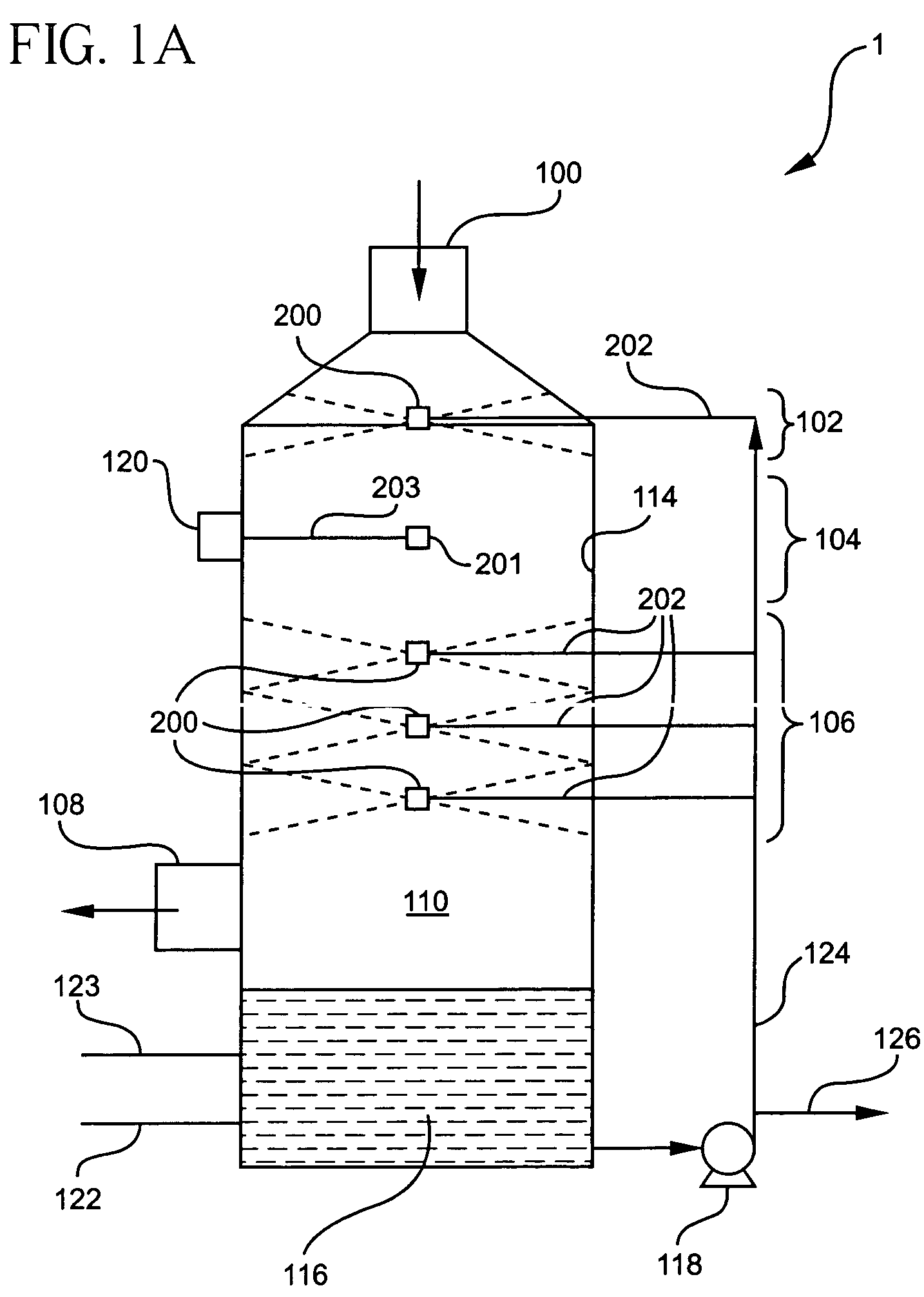
[0066] Referring to FIG. 1, the wet scrubber 1 is preferably a tall cylindrical tower and comprises a flue gas inlet 100, a gas quenching zone 102 in which the flue gas is quenched, an ozone injection and retention zone 104, a liquid spray zone 106, several layers of spray nozzles 200 located in the gas quenching zone 102 and liquid spray zone 106, and a flue gas exit 108. The diameter of the tower itself may range from 1.5-50 feet and its height may range from 5 to 120 feet.

[0067] High percentages of NOx removal from flue gas emitted from FCCU systems or similar systems can be achieved using the wet scrubber of the present inven...


PUM

PropertyMeasurementUnit
Temperatureaaaaaaaaaa

Abstract

An apparatus for controlling NOx emissions which includes a chamber having a wall surface and an interior, a flue gas entrance and a flue gas exit for a flue gas to enter and exit the interior of the chamber, a gas quenching zone in which the temperature of the gas can be lowered, an ozone injection and retention zone in the chamber, and a liquid spray zone including at least one spray nozzle for spraying a liquid towards the wall surface.

Description

CROSS REFERENCE TO RELATED APPLICATIONS [0001] This application claims the benefit of U.S. Provisional Application No. 60 / 485,780 filed Jul. 9, 2003.BACKGROUND OF THE INVENTION [0002] The present invention relates to a method and apparatus for controlling emissions of NOx in the flue gas from systems such as combustion and fluid catalytic cracking unit (FCCU) operations. More particularly, it is an improved wet scrubbing method and apparatus that utilizes a relatively mist-free or water-droplet free ozone injection and retention zone. [0003] The Clean Air Act Amendments were enacted in 1990 to regulate and reduce the amount of harmful pollutants released into the atmosphere. The Clean Air Act places strict guidelines on the amount of pollutants present in discharged flue gases from combustion sources and chemical plants. As a result, industries seek to implement efficient, but cost-effective systems and methods for controlling the release of harmful pollutants. [0004] Nitrogen oxide...

Claims


Application Information

Patent Timeline
IPC IPC(8): B01D53/56B01D53/79
CPCB01D53/56B01D53/79Y02C20/10B01D2257/402B01D2257/404B01D2251/104
Inventor HSIEH, JOSEPHGILMAN, KEVIN R.PHILIBERT, DOMINIQUEEAGLESON, SCOTTMORIN, ANDREW
Owner BELCO TECH
Learn More