In the detection step, the designer of the electronic system observes a
functional failure.
However, some
software debuggers also support limited
concurrency such as threaded program execution.
A major
disadvantage of software debuggers is, however, that they cannot be used for efficiently debugging general hardware of electronic systems.
For some components such
simulation models may not be readily available and must be generated.
Since the ideal testbench must correctly and exhaustively match the behavior of the target environment, creation of a testbench can be very difficult and
time consuming.
On the other hand, a testbench that is too simple will not provide the necessary coverage to find all the design errors.
Not only are the testbenches difficult to create, but also the more complex the HDL design is, the lower the performance of functional
simulation.
Accordingly, its low performance makes it impractical to use functional simulation either to debug real-time applications or to concurrently debug hardware and software of complex electronic systems.
Both techniques, functional simulation and
formal verification, have the major disadvantage that they do not operate on fabricated hardware.
Thus, their use is limited to debugging design errors.
As such, neither technique is applicable for debugging manufacturing faults, environment errors, timing errors and / or tool errors.
Also, inadequacies in the testbench have the potential to hide or introduce design errors in the HDL design during functional simulation which can later, when the HDL design is fabricated, show up as functional failures of the running electronic system.
However, since in-circuit emulators only work for the specific target CPU for which they were built, in-circuit emulators are inappropriate for debugging general digital circuits.
DFT techniques were originally developed for and applied to testing of manufacturing faults and have the major disadvantage that they do not relate back to the HDL description.
Thus
hardware emulation has the same disadvantage as functional simulation, namely, that it works on a model of the electronic system and not on the fabricated hardware.
As a result,
hardware emulation systems are limited to
design error debugging, and cannot be used for diagnosing manufacturing faults, tool errors, timing errors, etc.
In some cases the emulator speed may allow the user to connect the HDL design to the target environment which makes the design of testbenches unnecessary.
Even so, with the high speeds of state-of-the-art HDL designs,
hardware emulation is not capable of debugging the majority of real-time applications.
Another disadvantage is that the special synthesis, mapping, and multi-
chip partitioning steps required to bring an HDL design into a hardware emulation system are very complicated and
time consuming.
Application of
logic level debugging techniques to HDL design methodology is highly inefficient.
Since logic level debugging does not relate back to the HDL description, it normally would not provide the designer of the electronic system with sufficient information to correctly diagnose a
functional failure.
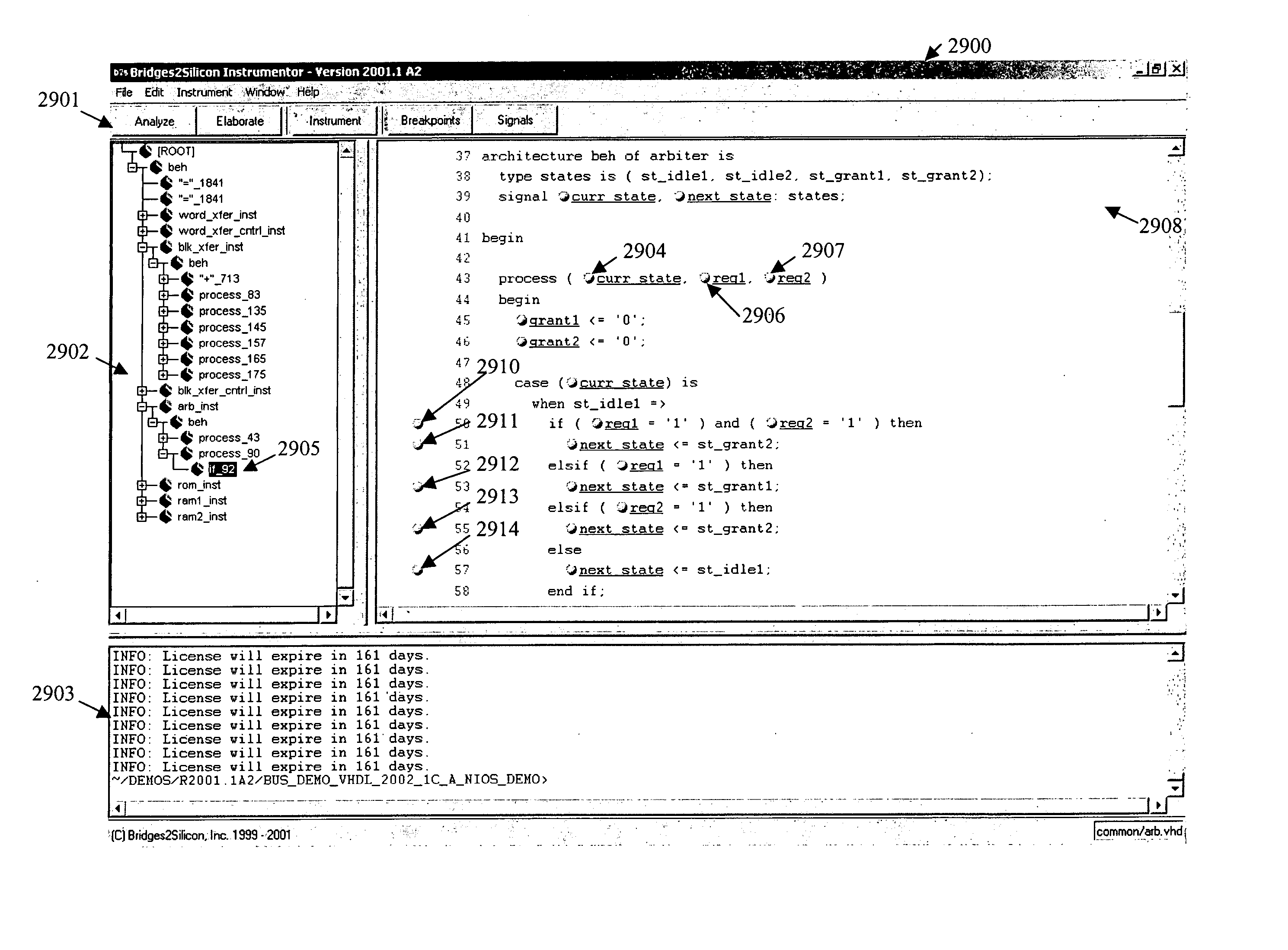
Although
source level emulation provides a debugging method which works at the level of the HDL description (in this case behavioral
VHDL), it has various drawbacks which limits its use in practice.
Second,
source level emulation does not allow the designer to perform customization.
For example, a designer is not able to select trade-offs between hardware overhead and debugging support.
Third,
source level emulation cannot
handle HDL descriptions on levels of abstraction other than the one provided by behavioral
VHDL.
Explicitly, source level emulation is not applicable for the most commonly used levels of abstraction of RTL HDL
and gate-level HDL.
Fourth, source level emulation supports neither hierarchy nor re-use of pre-designed blocks.
Fifth, there are various limitations and difficulties in relating registers back to behavioral HDL
source code.

