Apparatus and method for in-situ cleaning of a throttle valve in a CVD system

Inactive Publication Date: 2005-01-20
UPHAM ALLAN
View PDF21 Cites 12 Cited by
  • Summary
  • Abstract
  • Description
  • Claims
  • Application Information

AI Technical Summary

Benefits of technology

[0012] The present invention eliminates the aforementioned problems by providing an i

Problems solved by technology

However, some material also is inevitably deposited on other surfaces inside the chamber, and some material also may be deposited on the throttle valve.
As unwanted material is deposited on the throttle valve, the precise operation of the throttle valve is diminished, thereby compromising the precise control of the reactant gas pressure inside the reaction chamber.
However, the reactive species of the cleaning gas cannot reach the throttle valve for effective cleaning due to the limited lifetime of the reactive species.
Consequently, after multiple deposition and cleaning processes are performed in the chamber, a substantial amount of unwanted silicon oxide film is deposited and remains on the throttle valve, rendering it nonfunctional.
This poor pressure control in the reaction chamber contributes to the production of semiconductor devices having insufficient reliability.
Semiconductor wafers subsequently processed in the CVD chamber will be exposed to this foreign material, which will negatively impact manufacturing yield.
This problem of deposited material build-up on the throttle valve requires complete disassembly of the throttle valve assembly and manual cleaning by a wet chemistry techniq

Method used


Image

  • Apparatus and method for in-situ cleaning of a throttle valve in a CVD system
  • Apparatus and method for in-situ cleaning of a throttle valve in a CVD system
  • Apparatus and method for in-situ cleaning of a throttle valve in a CVD system

Examples


Example

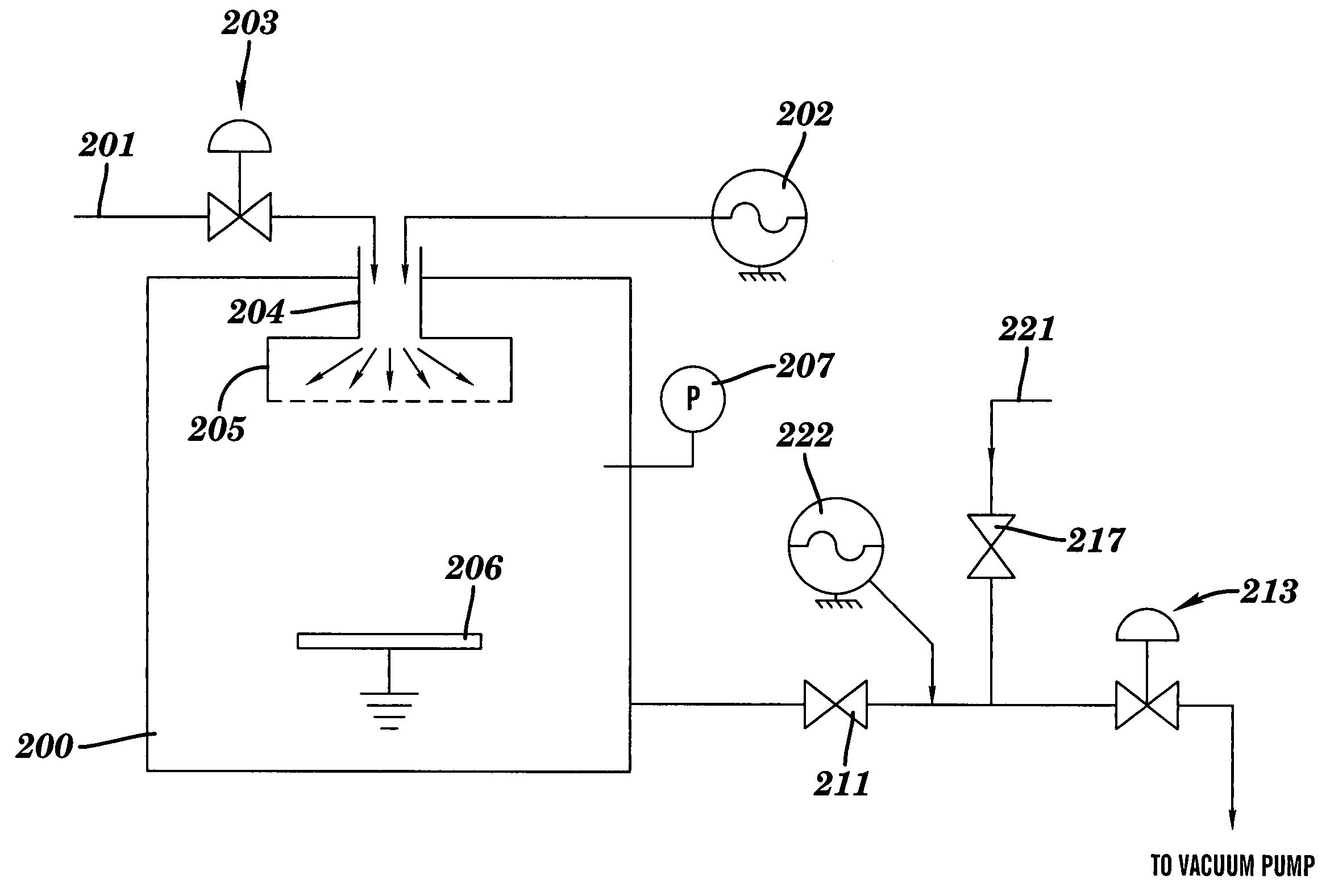
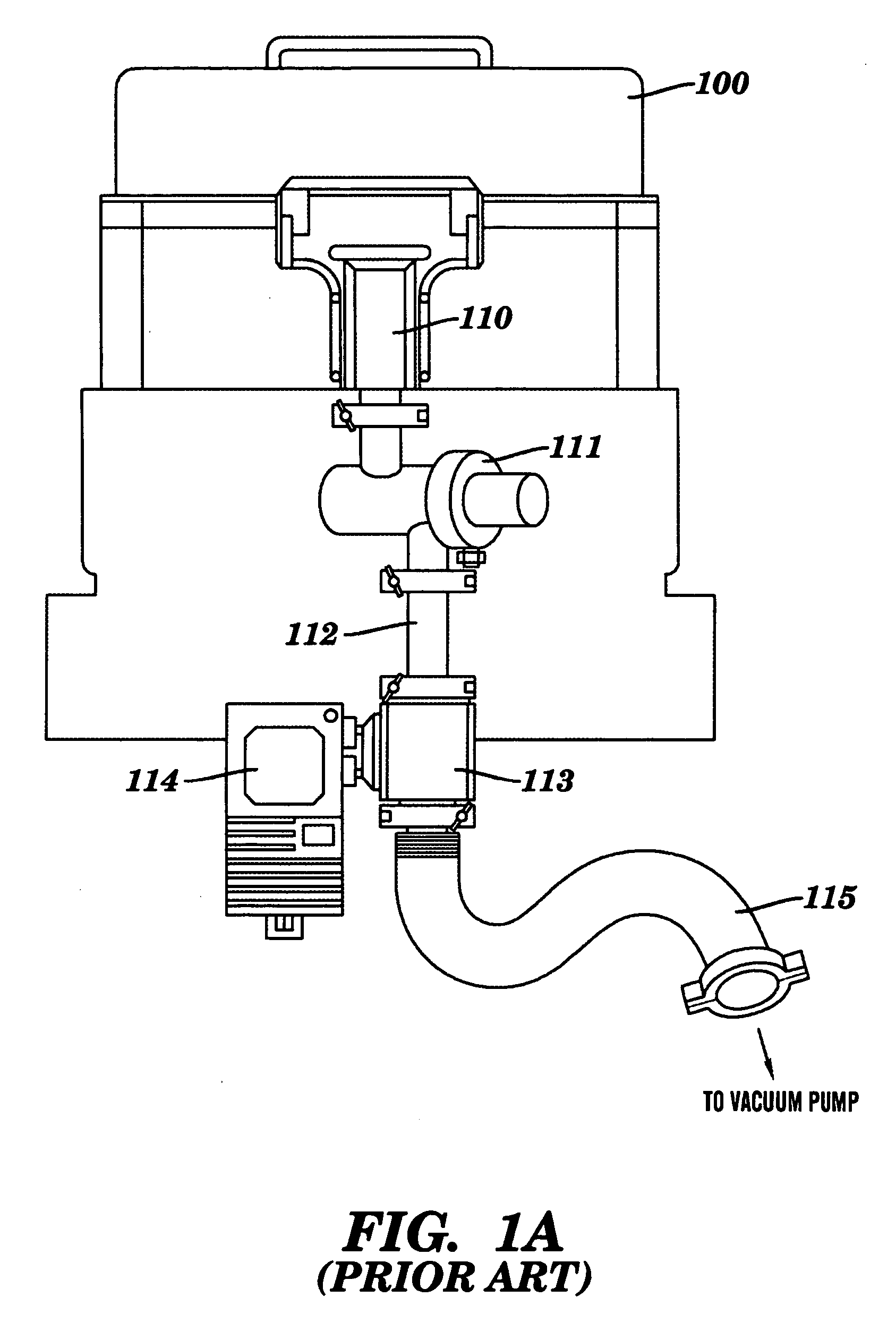
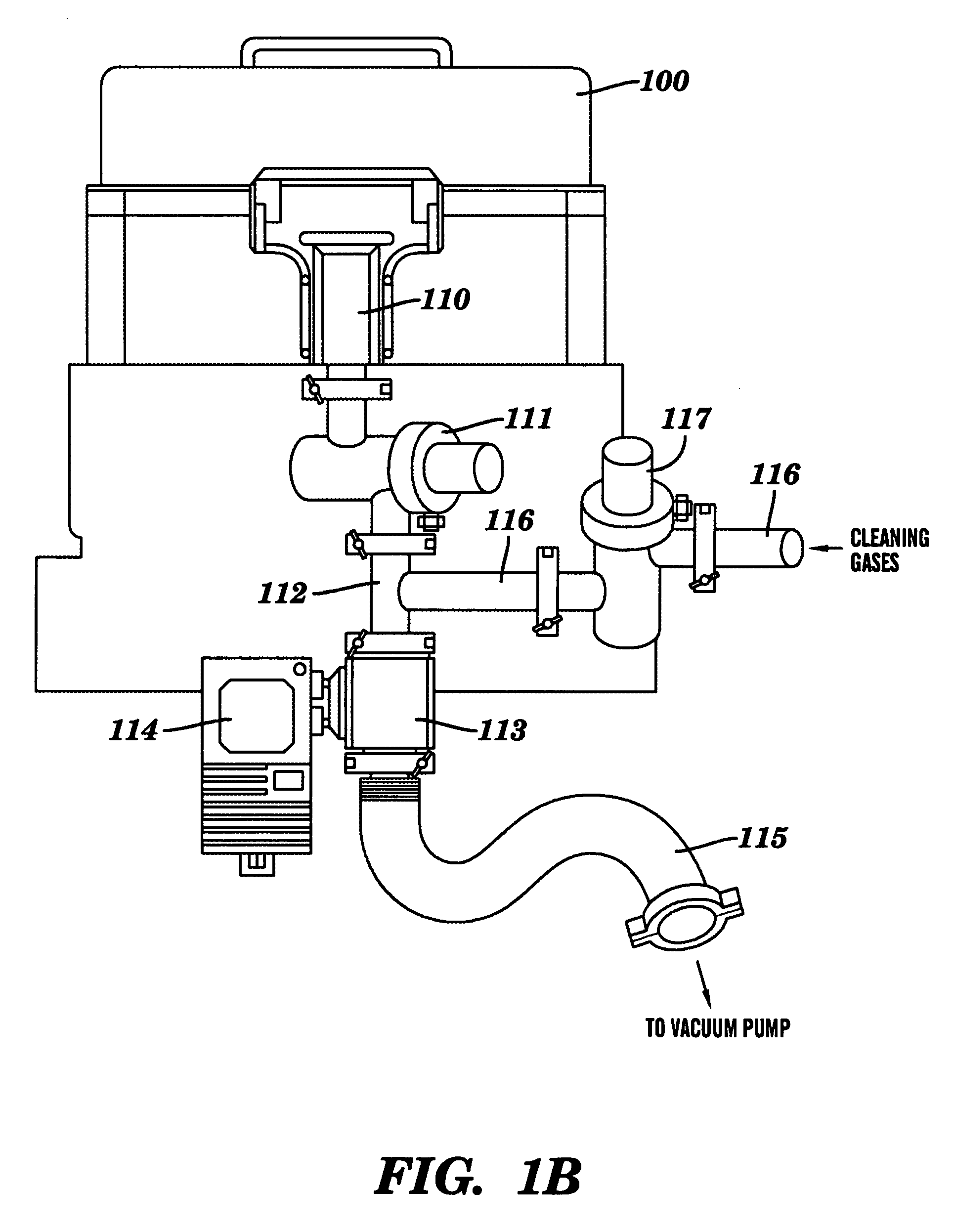
[0020]FIG. 1A shows a typical prior art exhaust flow control apparatus attached to a CVD system, such as the Precision 5000 System available from Applied Materials, Inc., Santa Clara, Calif. A CVD reaction chamber 100 for processing semiconductor wafers has an exhaust flow control apparatus attached to the side of the chamber through a flow adapter 110. Connected to the flow adapter 110 is a chamber isolation valve 111 for the opening and closing of the flow passage therein. Throttle valve 113 is connected to and in fluid communication with the chamber isolation valve 111 via exhaust pipe 112. Throttle valve 113 is controlled by a precision servo-motor 114 which is in turn controlled by closed-loop feedback signals received from a pressure manometer (not shown) attached to the CVD chamber 100. The gases exhausted from the CVD chamber 100 pass through flow adapter 110, chamber isolation valve 111, exhaust pipe 112 and throttle valve 113 into flow passage pipe 115 to a vacuum pump (no...


PUM

PropertyMeasurementUnit
Pressureaaaaaaaaaa
Poweraaaaaaaaaa
Poweraaaaaaaaaa

Abstract

The present invention relates generally to the field of semiconductor device manufacturing, and more specifically to an apparatus and method for in-situ cleaning of a throttle valve in a chemical vapor deposition (CVD) system. In the exhaust flow control apparatus of the CVD system, which comprises a chamber isolation valve, throttle valve and vacuum pump, means are provided for introducing cleaning gases downstream of the chamber isolation valve and upstream of the throttle valve. Such means may include a cleaning isolation valve connected to a cleaning gas source. Means for generating a reactive plasma of the cleaning gases, just before the throttle valve, may also be provided. During cleaning of the throttle valve, the CVD chamber is isolated, by closing the chamber isolation valve, and cleaning gases are flowed into the throttle valve, by opening the cleaning isolation valve.

Description

CROSS REFERENCE TO RELATED APPLICATIONS [0001] This application is a division of U.S. patent application Ser. No. 09 / 876,587 filed Jun. 7, 2001.FIELD OF THE INVENTION [0002] The present invention relates generally to the field of chemical vapor deposition (CVD) in semiconductor device manufacturing, and more specifically to a method for in-situ cleaning of a throttle valve in a CVD system. BACKGROUND OF THE INVENTION [0003] Chemical vapor deposition (CVD) processes are used widely in the manufacture of semiconductor devices. Generally, CVD involves exposing a semiconductor wafer to a reactive gas under carefully controlled conditions including elevated temperatures, sub-ambient pressures and uniform reactant gas flow rate, resulting in the deposition of a thin, uniform layer or film on the surface of the substrate. The undesired gaseous byproducts of the reaction are then pumped out of the deposition chamber. The CVD reaction may be driven thermally or by a reactant plasma, or by a ...

Claims


Application Information

Patent Timeline
IPC IPC(8): B08B7/00C23C16/44
CPCC23C16/4405B08B7/0035
Inventor UPHAM, ALLAN
Owner UPHAM ALLAN
Why Eureka
Try Eureka