Digital signal processing based implementation of a feed forward amplifier

a digital signal processing and amplifier technology, applied in the direction of amplifiers, amplifier modifications to reduce noise influence, electrical equipment, etc., can solve the problems of increasing the distortion of the signal, so as to reduce the distortion, reduce the fabrication cost, and increase the speed

Active Publication Date: 2005-01-20
HARRIS CORP
View PDF2 Cites 6 Cited by
  • Summary
  • Abstract
  • Description
  • Claims
  • Application Information

AI Technical Summary

Benefits of technology

[0026] It is another object of the present invention to provide a feed forward amplifier which incorporates the elements of both digital pre-distortion and feed forward architecture in order to reduce the problems with both.
[0027] It is a further object of the present invention to provide a feed forward amplifier using digital signal processing which reduces the fabrication costs and increases the speed at which such a feed forward amplifier can operate.

Problems solved by technology

However, a common problem associated with such signal enhancement is the addition of amplifier noise and distortion to the electrical signal.
It is also known that at higher power these power amplifiers are more likely to distort the signal in some way.
Most of the modern transmission signals have limitations on how much distortion is permissible.
Achieving power amplification which is cost effective, efficient (i.e., does not require a lot of external power), small sized, and achieves adequate linearity has become a challenge to modern designers of these devices.
Conventional feed forward power amplifiers utilize delay lines that typically are bulky and cause unneeded circuit loss.
Often exotic and costly substrates such as glass or ceramic loaded Teflon™ are utilized.
A limiting factor in DSP has been the speed of analog to digital conversion, and digital to analog conversion; however, recent technology has overcome these problems.
These are unwanted spurious signals.
In practice, this is difficult to accomplish completely, but typical systems achieve 30 to 40 dB (decibels) of cancellation.
What is expected to remain are the error signals which are the unwanted signal components (i.e., noise and distortion, including spurious signals).
There can be, however, a number of issues with this approach.
First, because the high power output of the main amplifier 6 must be delayed, there is loss in the delay element.
Low cost delay elements are delay lines which have higher loss than delay filters but the latter are expensive.
Typical losses are 0.5 dB which means that ten percent (10%) of the power is lost.
Second, because the cancellation process is approximate, the amplified error signal contains a considerable amount of desired signal.
As a result, the error amplifier 12 must be quite large and utilizes a lot of power, thus further reducing the efficiency of the overall amplifier.
Third, the ultimate efficiency of a feed forward amplifier is limited, based on the first and second reasons set forth above.
Fifth, as a result of the basic architecture and components required, feed forward amplifiers tend to be complex which affects their reliability and cost.
Of course, there is no mechanism to develop more output power than can be delivered by the power amplifier output stage.
Another issue is “memory effect” which is so labeled because the status of the amplitude prior to the signal being amplified affects both the phase shift and the gain of the amplifier.
Typical digital pre-distorted power amplifiers do not achieve the level of performance of feed forward amplifiers.

Method used


Image

  • Digital signal processing based implementation of a feed forward amplifier
  • Digital signal processing based implementation of a feed forward amplifier
  • Digital signal processing based implementation of a feed forward amplifier

Examples


Embodiment Construction

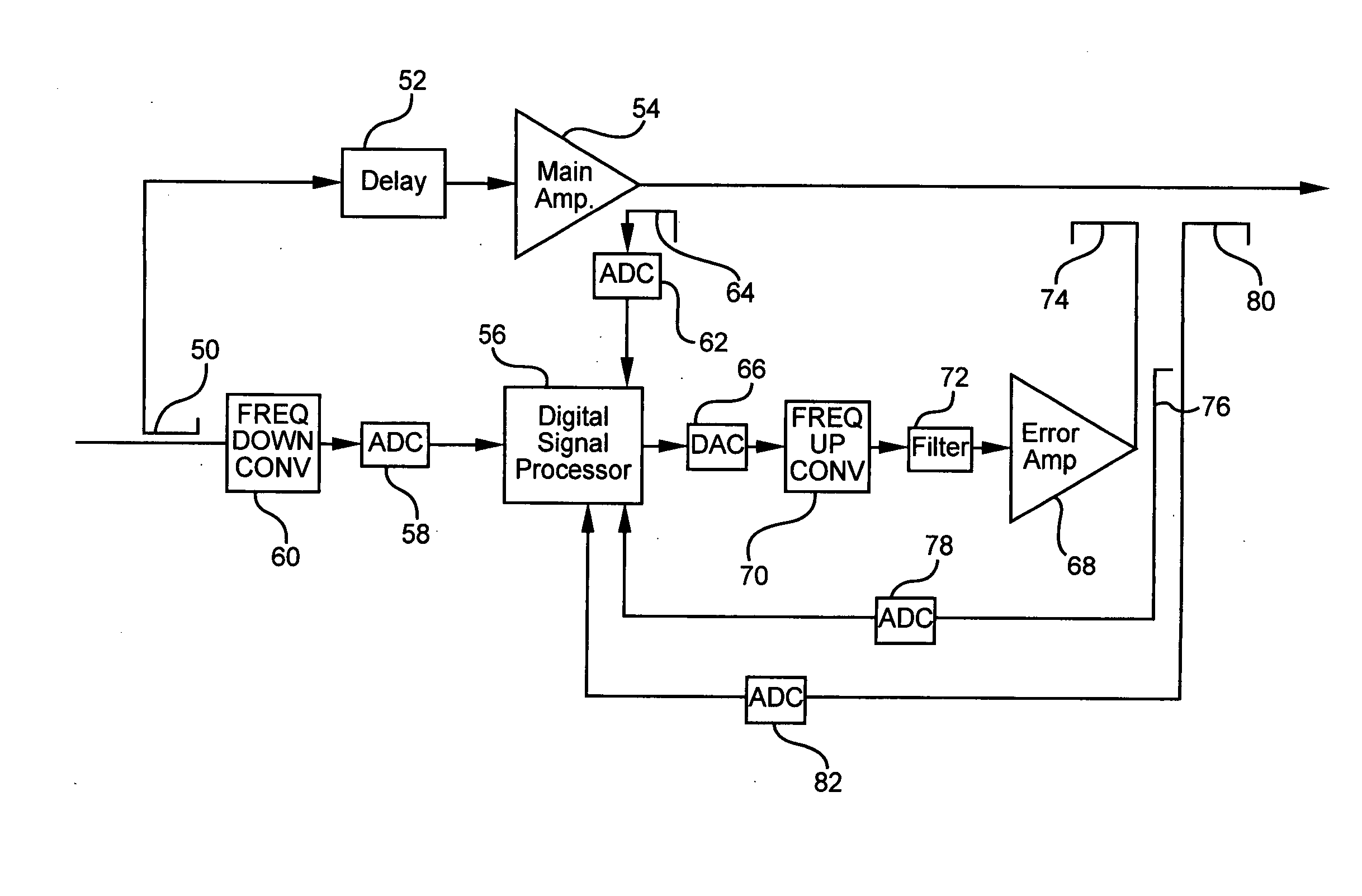
[0044] The present invention combines elements of feed forward amplifiers, digital pre-distortion amplifiers and digital signal processing (DSP) techniques. The present invention offers a number of improvements to conventional feed forward power amplifier architecture. The circuitry and methodology of the present invention involve manipulating digital signals derived from RF (radio frequency) frequencies so as to simulate the distortion in a main amplifier. The distortion signal is then amplified in an error amplifier and subtracted from the output of the main amplifier to leave the desired signal. The circuitry and methodology of the present invention incorporate elements of both digital pre-distortion and feed forward architecture in order to reduce the problems with both and to take advantage of the great strides that have been made in digital signal processing both in cost and speed.

[0045] Turning initially to FIG. 4 of the drawings, one embodiment of a feed forward amplifier f...


PUM


Abstract

A digital signal processing based feed forward amplifier includes a delay circuit which receives a portion of the input signal and generates a delayed input signal. A first analog to digital converter receives another portion of the input signal and generates a digitized input signal. A main amplifier receives the delayed input signal and generates a main amplified signal. A second analog to digital converter receives at least a portion of the main amplified signal and converts it to a digitized main amplified signal. A digital signal processor receives the digitized input signal and the digitized main amplified signal and generates a digitized error signal. The digitized error signal is converted to an analog error signal by a digital to analog converter. An error amplifier receives the analog error signal and amplifies it to generate an amplified error signal. This error signal includes a noise and distortion component which is substantially the same in magnitude as the noise and distortion component of the main amplified signal. The amplified error signal and the main amplified signal are combined so that the noise and distortion components of each subtract, leaving substantially only the amplified desired signal component remaining in the amplified input signal, which is outputted by the feed forward amplifier. A third analog to digital converter converts a portion of the amplified error signal to a digitized amplified error signal, and a fourth analog to digital converter converts a portion of the output signal to a digitized output signal. The digitized output signal and the digitized amplified error signal are provided to the digital signal processor which generates the digitized error signal in response thereto.

Description

CROSS REFERENCE TO RELATED APPLICATION [0001] This application claims the benefit of U.S. provisional patent application Ser. No. 60 / 475,228, filed on Jun. 2, 2003, and entitled “A DSP (Digital Signal Processing) Based Implementation of a Feed Forward Amplifier”, the disclosure of which is incorporated herein by reference.BACKGROUND OF THE INVENTION [0002] 1. Field of the Invention [0003] This invention relates generally to distortion canceling techniques and more specifically relates to feed forward circuits and techniques for altering the amount of signal noise and distortion provided by amplifying devices. [0004] 2. Description of the Prior Art [0005] Amplifiers are customarily used for enhancing electrical signals. However, a common problem associated with such signal enhancement is the addition of amplifier noise and distortion to the electrical signal. This is especially true when power amplifiers are utilized. Traditionally, feed forward circuits and techniques have been used...

Claims


Application Information

Patent Timeline
Patent Type & Authority Applications(United States)
IPC IPC(8): H03F1/26H03F1/32
CPCH03F1/3229H03F1/26
Inventor POSNER, RICHARD D.BEASLEY, JAMES
Owner HARRIS CORP
Why Eureka
Try Eureka