Configurable heat sink with matrix clipping system
- Summary
- Abstract
- Description
- Claims
- Application Information
AI Technical Summary
Benefits of technology
Problems solved by technology
Method used
Image
Examples
Embodiment Construction
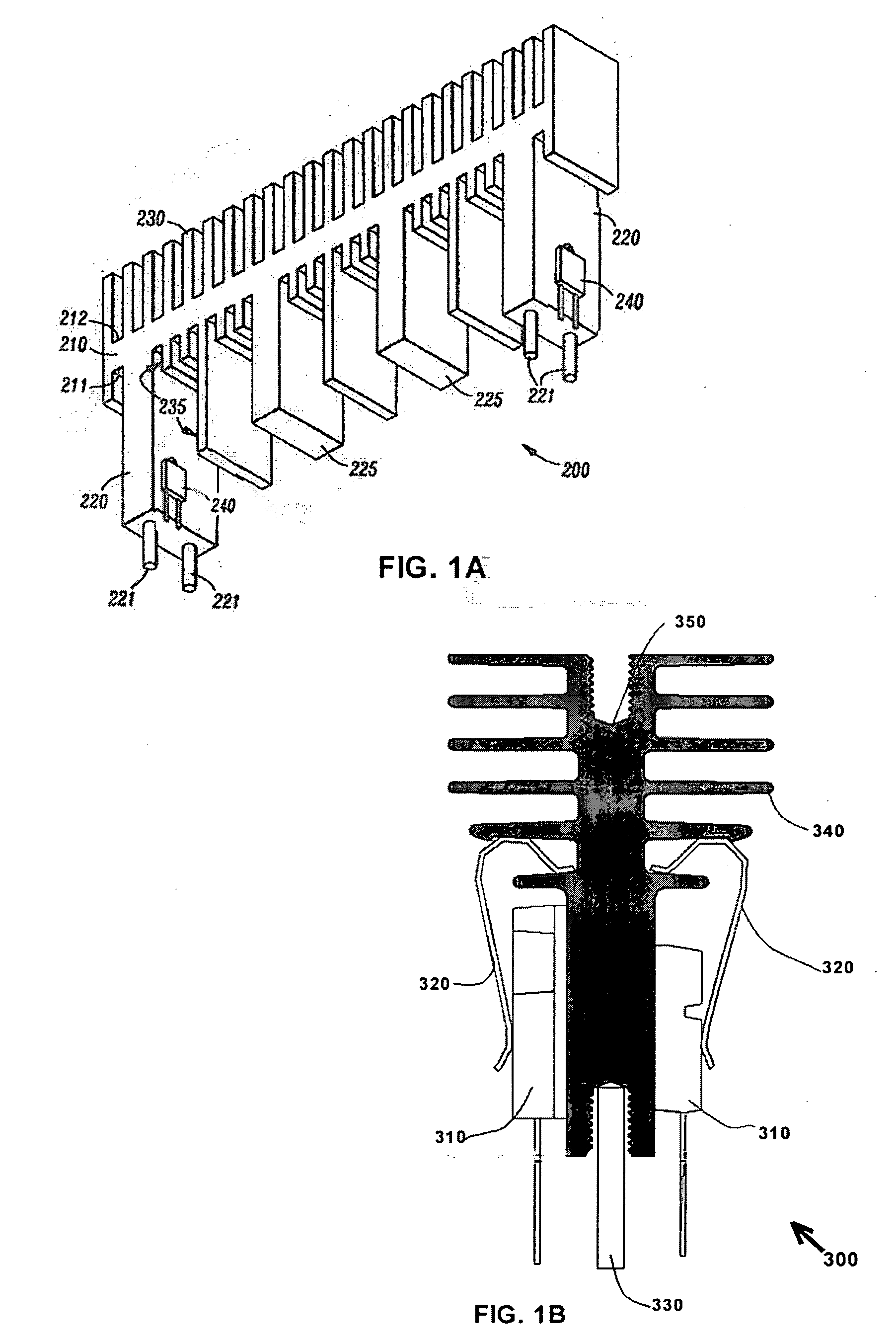
[0023] Referring initially to FIGS. 1A and 1B, illustrated are examples of prior art heat sinks 200, 300. The prior art heat sink 200 illustrated in FIG. 1A has a longitudinal spine 210 with an opposing first side 211 and second side 212. Extending from the first side 211 of the spine 210 are electronic device support legs 220, 225, configured so that each leg 220, 225 can support two electronic devices or components on opposing side of the support legs 220, 225, as shown, an electronic component 240 mounted a clip (not shown here), Multiple cooling fins 230, 235 are extending from the second side 212 and first side 211 of the spine 210. Apparently this heat sink has the disadvantages of: 1) fixed orientation mounting with given air flow direction to manipulate the printed wiring or circuit layout; 2) lack of unitary construction since the clip is a separated part; 3) secondary machining operation is required to make the port for receiving pin 221, if the heat sink is manufactured b...
PUM
 Abstract
Description
Claims
Application Information
 - R&D
- Intellectual Property
- Life Sciences
- Materials
- Tech Scout
- Unparalleled Data Quality
- Higher Quality Content
- 60% Fewer Hallucinations
Browse by: Latest US Patents, China's latest patents, Technical Efficacy Thesaurus, Application Domain, Technology Topic, Popular Technical Reports.
© 2025 PatSnap. All rights reserved.Legal|Privacy policy|Modern Slavery Act Transparency Statement|Sitemap|About US| Contact US: help@patsnap.com


