
Acoustic wave ice and water detector

a detector and acoustic wave technology, applied in the field of acoustic wave sensors, can solve the problems of high system cost, extremely complex analysis of signal, and inability to detect the presence of ice or other contaminants, and achieve the effect of simple manufacturing

Inactive Publication Date: 2005-01-27
TEXZEC
View PDF28 Cites 11 Cited by
  • Summary
  • Abstract
  • Description
  • Claims
  • Application Information

AI Technical Summary

Benefits of technology

In accordance with the present invention, the disadvantages of prior acoustic wave sensors, and in particular ice detectors, have been overcome. In accordance with the present invention, an acoustic wave sensor and method utilize one or more acoustic waves trapped in an acoustic wave cavity to detect the presence of one or more substances on a surface of the acoustic wave cavity. The senor of the present invention is simple to manufacture and inexpensive. Malfunctioning of the sensor can be detected from the sensor itself without a manual inspection of the sensor. Moreover, in accordance with one embodiment of the present invention, access to the sensor can be had from an external side of the member on which the sensor is mounted, for example an airplane wing.
In accordance with one embodiment of the present invention, an ice detector includes an acoustic wave cavity formed in a substrate and defined by an area of increased mass. At least one transducer is positioned adjacent the acoustic wave cavity so that when driven, the transducer generates in the acoustic wave cavity a trapped acoustic wave that is sensitive to ice and insensitive to water. The transducer also provides a signal representing the trapped acoustic wave in the acoustic wave cavity. A simple and inexpensive circuit is responsive to the transducer signal to detect the presence of ice. In one embodiment of the present invention, the transducer is positioned with respect to the acoustic wave cavity to generate a torsional acoustic wave that is trapped in the cavity.

Problems solved by technology

Because these systems use acoustic wave energy that propagates over a substantial length of an airplane wing, the analysis of the signal, representing the acoustic wave energy picked up by the receiver transducer, to determine the presence of ice or other contaminants is extremely complex.
As a result, these systems are very expensive.
This can be extremely difficult.
As a result of this sensitivity, when the shear acoustic wave switch is used in the presence of water, the level of which varies, such as when the switch is used outdoors in rain, the water can cause the switch to have a response that flickers.
However, the cylindrical body, in which the torsional wave is trapped, greatly limits the application and use of trapped torsional modes.

Method used


Image

  • Acoustic wave ice and water detector
  • Acoustic wave ice and water detector
  • Acoustic wave ice and water detector

Examples


Embodiment Construction

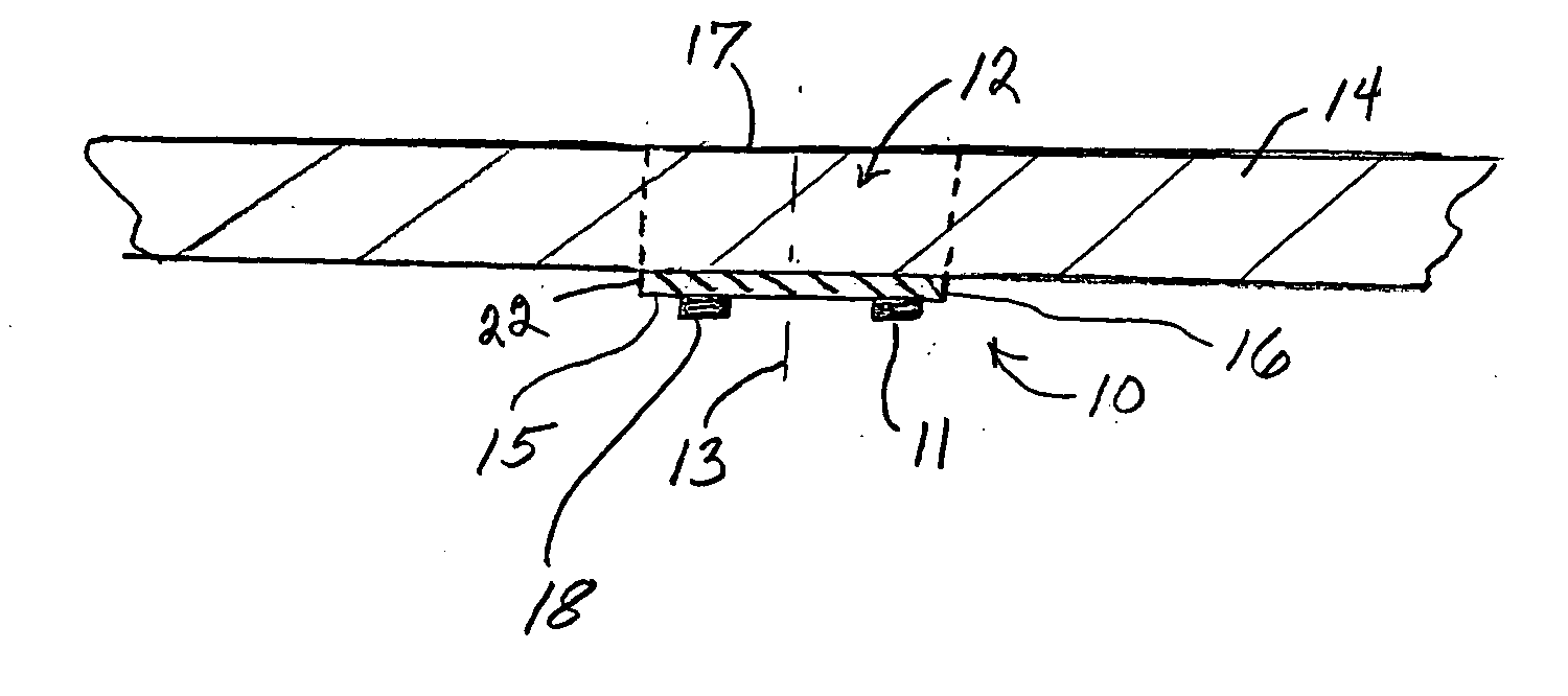
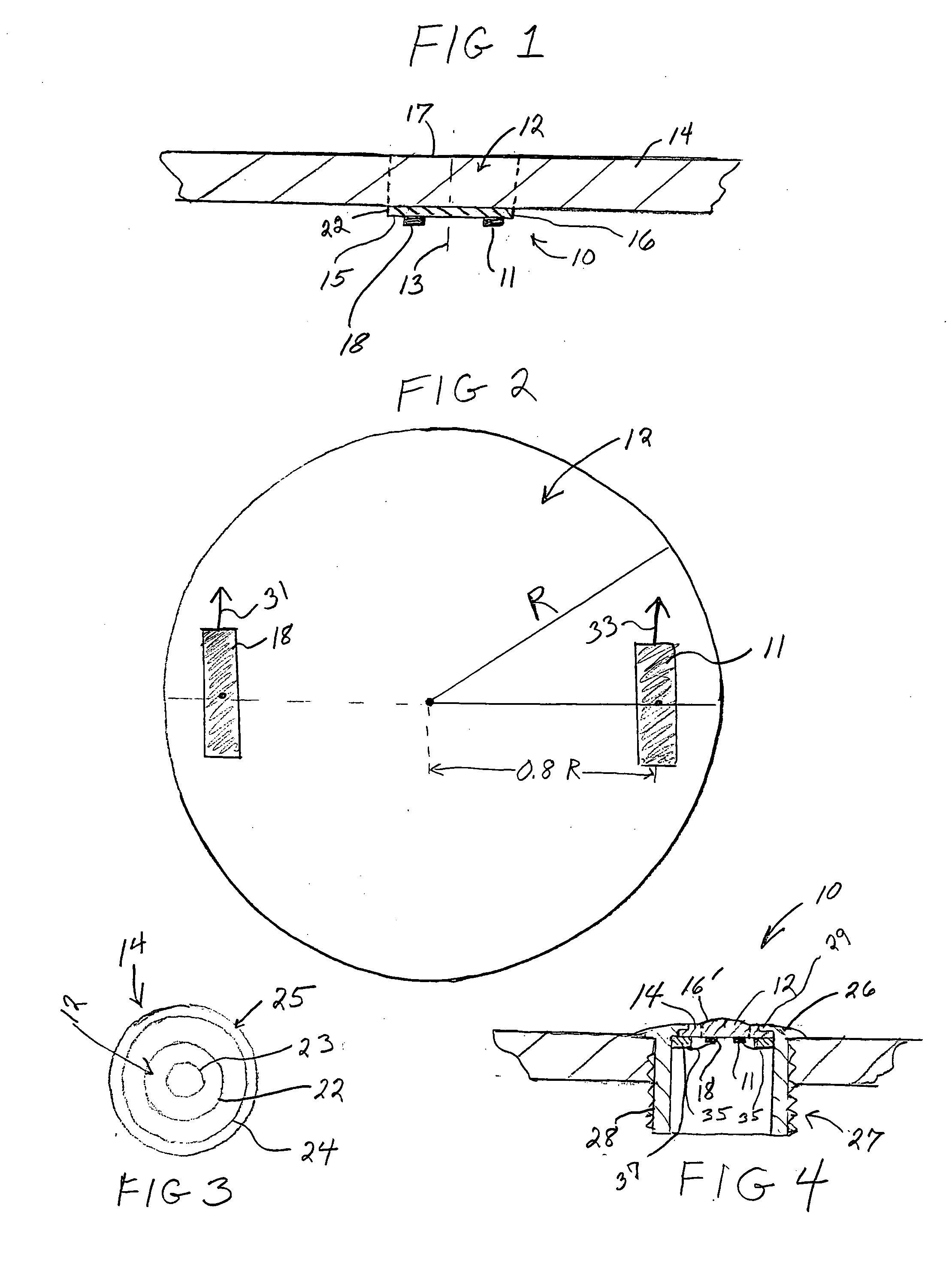
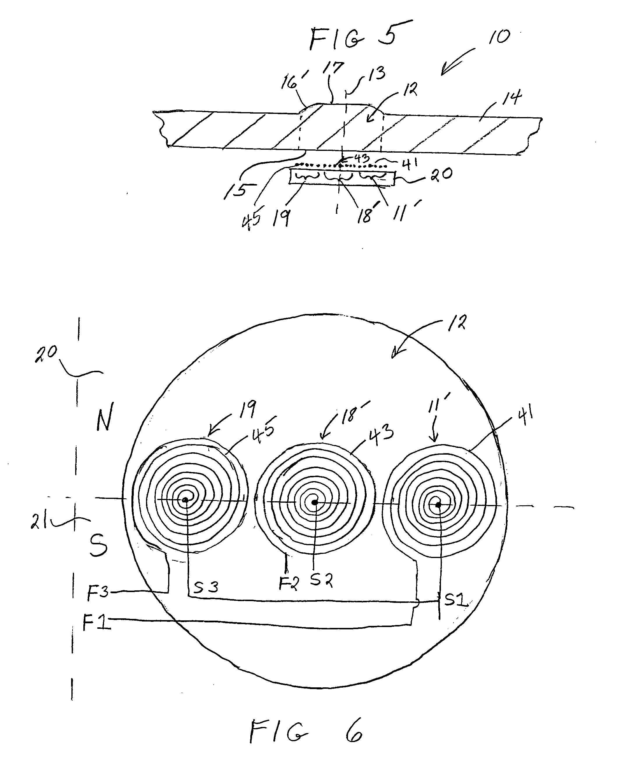
An acoustic wave sensor 10, in accordance with the present invention as shown in FIGS. 1-6, includes a transducer 11, 11′ positioned adjacent an acoustic wave cavity 12 such that the transducer 11, 11′ is off-center with respect to the centerline 13 of the cavity 12 to generate a trapped or resonant torsional acoustic wave in the acoustic wave cavity 12. The acoustic wave cavity 12 is formed in a noncylindrical substrate 14 wherein the transducer 11, 11′ generating the trapped torsional acoustic wave is in a plane that is parallel to a planar surface 15 of the acoustic wave cavity 12. Because torsional waves can be trapped in a cylindrical substrate, the acoustic wave cavity of the sensor 10 can also be formed in a cylindrical substrate. It has been found that a trapped, torsional acoustic wave generated in accordance with the present invention is sensitive to a first substance such as ice contacting a surface 17 of the acoustic wave cavity but is insensitive to water. That is, an ...


PUM


Abstract

An acoustic wave sensor utilizes one or more acoustic waves trapped in an acoustic wave cavity to detect the presence of one or more substances on a surface of the acoustic wave cavity. To detect the presence of ice, a trapped torsional acoustic wave is used. To detect water, an acoustic wave with flexural or compressional components is used. The sensor includes a number of transducers adjacent the acoustic wave cavity where a controller drives different sets of the transducers to generate different acoustic waves.

Description

STATEMENT REGARDING FEDERALLY SPONSORED RESEARCH OR DEVELOPMENT N / A FIELD OF INVENTION The present invention relates to an acoustic wave sensor utilizing one or more acoustic waves trapped in an acoustic wave cavity for detecting the presence of one substance or more than one substance on the surface of the cavity. In one embodiment, the acoustic wave sensor forms an ice detector and in another embodiment, the sensor forms and ice and water detector although the acoustic wave sensor of the present invention can be used to sense the presence of other substances as well. BACKGROUND OF THE INVENTION Ice detectors are known that utilize acoustic waves propagating over a distance through a structure, such as the outer material of an airplane wing, wherein the acoustic waves propagate between a transmitter transducer and a receiver transducer. Propagating waves are used in these systems to detect the presence of ice along the length of the airplane wing structure through which the wave...

Claims


Application Information

Patent Timeline
IPC IPC(8): B64D15/20G01M7/00G01N29/00G01N29/02G01N29/22G01N29/34G01N29/44G01W1/00G08BG08B19/02H04B1/02H04R17/00
CPCB64D15/20G01N29/11G01N29/22G01N29/34G01N29/4427G01N2291/023G01N2291/105G01N2291/02827G01N2291/0422G01N2291/0426G01N2291/0427G01N2291/044G01N2291/0251
Inventor KNOWLES, TERENCE J.KALMUS, CHRIS
Owner TEXZEC
Learn More