Gas sensor

a technology of gas sensor and sensor element, applied in the field of gas sensor, can solve the problems of delay in response of gas sensor, water resistance, water resistance, etc., and achieve the effect of effective protection of the sensor element, and reducing the temperature change of the sensor elemen

Active Publication Date: 2005-01-27
NGK INSULATORS LTD
View PDF13 Cites 14 Cited by
  • Summary
  • Abstract
  • Description
  • Claims
  • Application Information

AI Technical Summary

Benefits of technology

The present invention has been made taking the foregoing problems into consideration, and an object thereof is to provide a gas sensor which makes it possible to effectively protect a sensor element from the droplets of ...

Problems solved by technology

As for the conventional protective covers as described above, if a water protective cover is used, the response of the gas sensor may be delayed.
If the sensor and the cover are installed downstream with respect to the catalyst, a problem was found in relation to water resistance (performance to avoid condensed water produced upon the start-up of the engine).
Further, another problem was found in relation to water resistance depending on the angle of attachment to the exhaust tube of the interna...

Method used


Image

  • Gas sensor
  • Gas sensor
  • Gas sensor

Examples


first embodiment

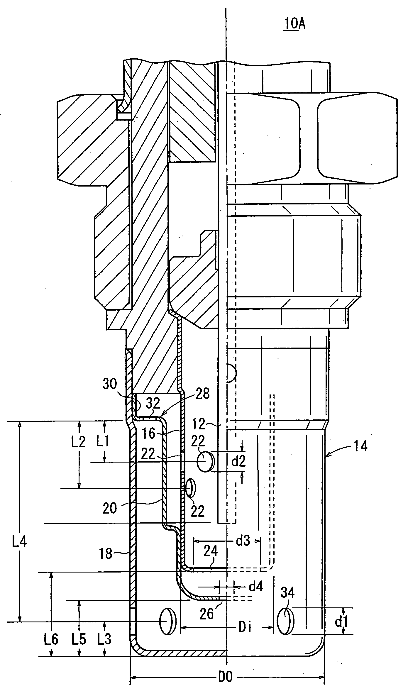
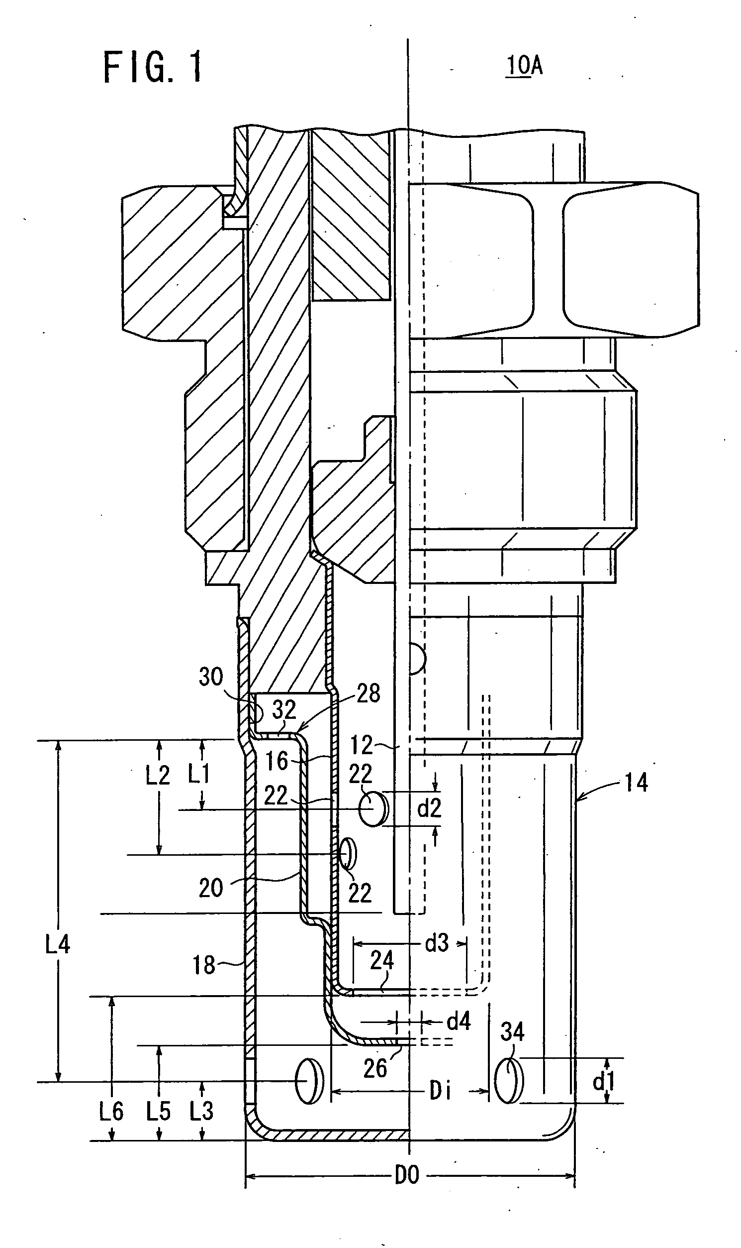
As shown in FIG. 1, a gas sensor 10A comprises a sensor element 12 which measures a predetermined gas component, for example, NOx contained in a measurement gas (exhaust gas), and a protective cover 14 which is arranged to surround an end portion of the sensor element 12.

The sensor element 12 is constructed in the same manner as a sensor element described, for example, in Japanese Laid-Open Patent Publication No. 2000-304719 (see FIGS. 3 and 4 of this patent document). Therefore, the explanation thereof will be herein omitted.

In the gas sensor 10A according to the first embodiment, the protective cover 14 surrounding the sensor element 12 comprises an inner protective cover 16 which covers the end portion of the sensor element 12, an outer protective cover 18 which covers the inner protective cover 16, and an intermediate protective cover 20 which is installed between the inner protective cover 16 and the outer protective cover 18.

The inner protective cover 16 is formed of met...

example 1

was constructed such that the ratio A1 / A2 was not less than 1, and the diameter of the outer gas inlet holes 34 was smaller than that of Comparative Example 2 was prepared such that the ratio A1 / A2 was not less than 1, and the number of the inner gas inlet holes 22 was larger than that of Comparative Example 1. Example 3 was prepared in the same manner as the gas sensor 10A according to the first embodiment described above, in which the ratio A1 / A2 was not less than 1, the diameter of the outer gas inlet holes 34 was smaller than that of Comparative Example 1, and the number of the inner gas inlet holes 22 was larger than that of Comparative Example 1.

FIG. 6 shows results of the measurement of wetting, and FIG. 7 shows results of the measurement of the temperature change of the sensor element 12. In FIG. 7, left bars indicate the cases of the standard attachment, and right bars indicate the cases of the inclined attachment.

FIG. 6 shows the result of measurement of wetting. In the ...

second embodiment

Next, a gas sensor 10B will be explained with reference to FIG. 18.

The gas sensor 10B according to the second embodiment is configured in approximately the same manner as the gas sensor 10A according to the first embodiment described above. However, as shown in FIG. 18, the gas sensor 10B is different from the gas sensor 10A in that plate sections 40 are provided for the inner protective cover 16 to extend over rectangular inner gas inlet holes 22, and the number of the inner gas inlet holes 22 is six.

Further, the gas sensor 10B is also different from the gas sensor 10A in that the flange section 28 of the intermediate protective cover 20 is positioned lower than that in the first embodiment, and the positional relationship of the outer gas inlet holes 34, the slits 32, and the inner gas inlet holes 22 is established such that the outer gas inlet holes 34, the slits 32, and the inner gas inlet holes 22 are arranged in this order from the bottom to an upper part of the outer prot...


PUM


Abstract

A protective cover of a gas sensor includes an inner protective cover which covers at least an end portion of a sensor element, an outer protective cover which covers the inner protective cover, and an intermediate protective cover which is installed between the inner protective cover and the outer protective cover. A1/A2≧1 provided that A1 represents a total opening area of the inner gas inlet holes provided for the inner protective cover, and A2 represents a total opening area of the outer gas inlet holes provided for the outer protective cover.

Description

BACKGROUND OF THE INVENTION 1. Field of the Invention: The present invention relates to a gas sensor for measuring gas components such as NO, NO2, SO2, CO2, and H2O, contained in the atmospheric air or the exhaust gas discharged from vehicles or automobiles, for example. In particular, the present invention relates to a gas sensor which has a protective cover surrounding a sensor element. 2. Description of the Related Art: A variety of gas sensors have been suggested and practically used. For example, there are oxygen sensors based on the use of oxygen ion conductors, NOx sensors (see Japanese Laid-Open Patent Publication No. 8-271476), HC sensors (see Japanese Laid-Open Patent Publication No. 8-247995), hydrogen sensors based on the use of proton ion conductors, H2O sensors, oxygen sensors based on the use of oxide semiconductors such as SnO2 and TiO2. Among the gas sensors as described above, the oxygen sensor based on the use of ZrO2 and the oxygen sensor based on the use of...

Claims


Application Information

Patent Timeline
IPC IPC(8): G01N27/409G01N27/12G01N27/406G01N27/407G01N27/416
CPCG01N27/4077
Inventor IKOMA, NOBUKAZUMIYASHITA, TAKEYAMUROGUCHI, AKIHIRO
Owner NGK INSULATORS LTD
Why Eureka
Try Eureka