Liquid crystal display and manufacturing method thereof

a technology of liquid crystal display and manufacturing method, which is applied in the field of liquid crystal display, can solve the problems of stitch defect generation on the screen of the liquid crystal display, inaccurate shot alignment, and defects in stitching

Active Publication Date: 2005-01-27
SAMSUNG DISPLAY CO LTD
View PDF2 Cites 16 Cited by
  • Summary
  • Abstract
  • Description
  • Claims
  • Application Information

AI Technical Summary

Benefits of technology

[0008] A motivation of the present inventio

Problems solved by technology

Since transition, rotation, distortion, and etc. are generated during light exposure, the shots are not aligned accurately.
Therefore, the stitch defect is generated on the screen of the LCD due to brightness discontinuity betwee

Method used


Image

  • Liquid crystal display and manufacturing method thereof
  • Liquid crystal display and manufacturing method thereof
  • Liquid crystal display and manufacturing method thereof

Examples


Embodiment Construction

[0034] The present invention now will be described more fully hereinafter with reference to the accompanying drawings, in which embodiments of the invention are shown. The present invention may, however, be embodied in many different forms and should not be construed as limited to the embodiments set forth herein.

[0035] In the drawings, the thickness of layers, films and regions are exaggerated for clarity. Like numerals refer to like elements throughout. It will be understood that when an element such as a layer, film, region or substrate is referred to as being “on” another element, it can be directly on the other element or intervening elements may also be present. In contrast, when an element is referred to as being “directly on” another element, there are no intervening elements present.

[0036] Then, liquid crystal displays and manufacturing methods thereof according to embodiments of the present invention will be described with reference to accompanying drawings.
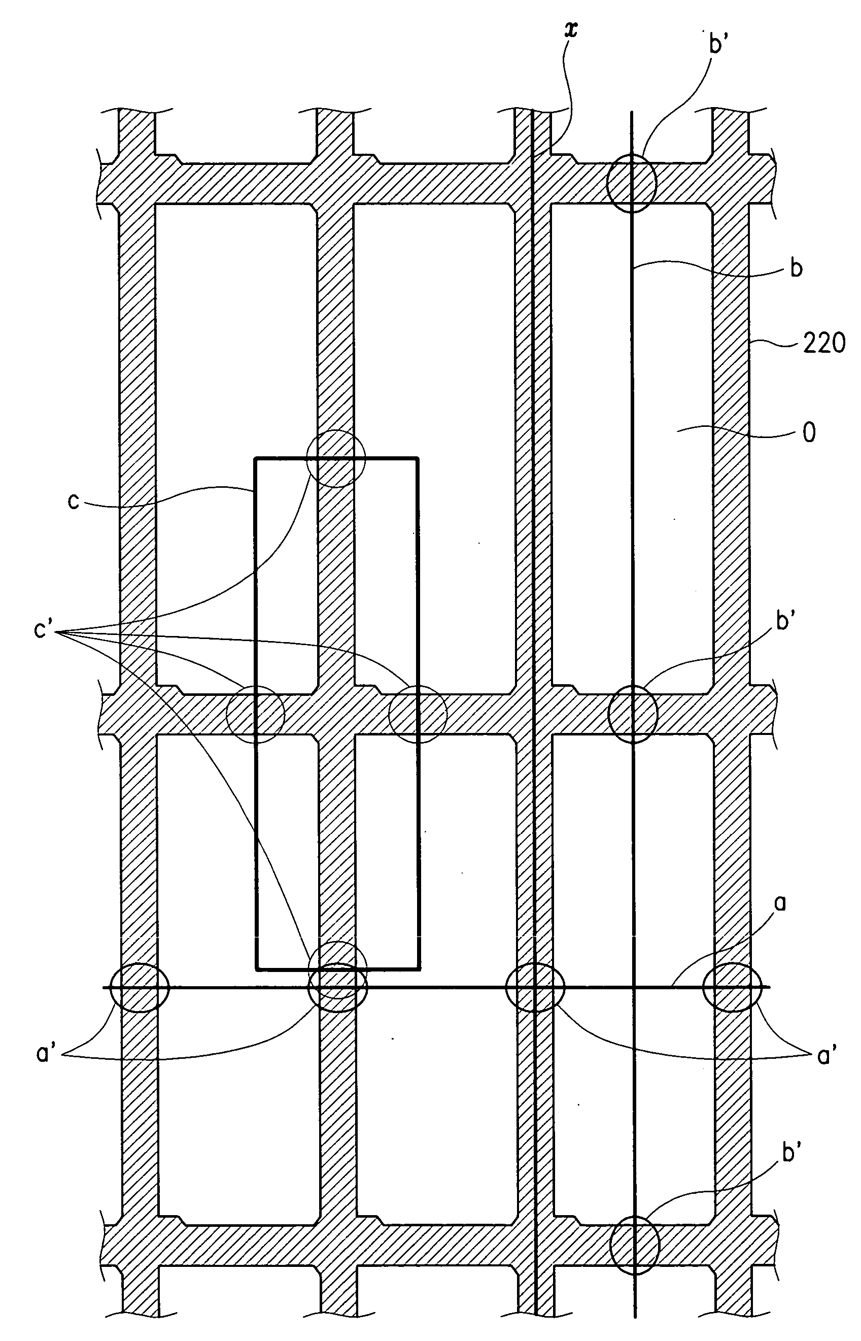
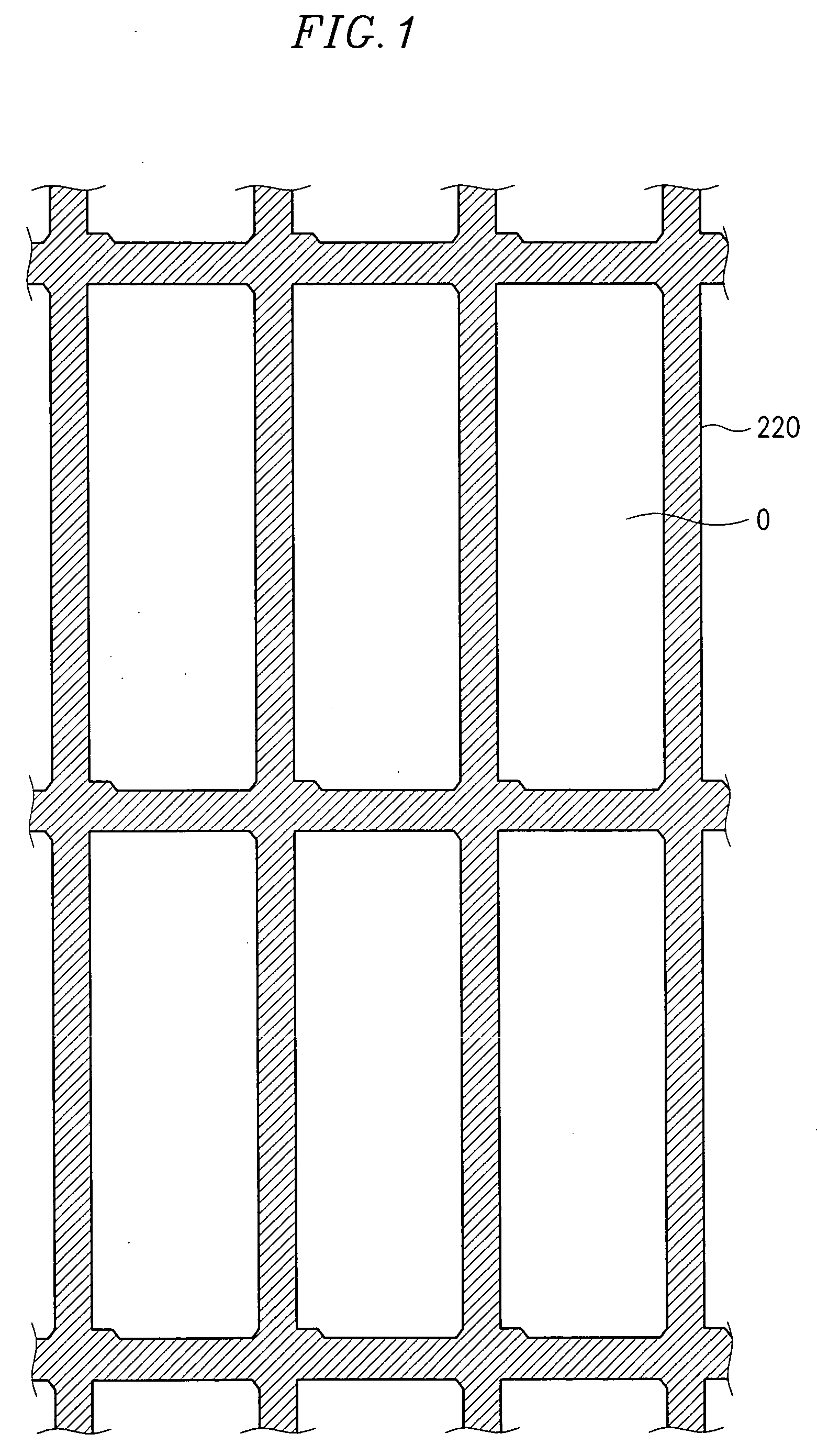
[0037]FIG. 1...


PUM


Abstract

A method of manufacturing a liquid crystal display panel is provided, which includes: coating a negative organic photoresist on a substrate; performing divisional light exposure with a plurality of shots including first and second shots adjacent to each other; and developing the photoresist to form a light blocking member having a plurality of openings, wherein the first and the second shots have a boundary crossing the openings.

Description

BACKGROUND OF THE INVENTION [0001] (a) Field of the Invention [0002] The present invention relates to a liquid crystal display and a manufacturing method of a liquid crystal display. [0003] (b) Description of Related Art [0004] A display device such as a liquid crystal display (LCD) includes a plurality of pixels arranged in a matrix, and each pixel includes a transparent pixel electrode for displaying images. The pixel electrodes are driven by signals from signal lines including gate lines and data lines that intersect each other to define pixel areas and are connected to the pixel electrodes through switching elements such as thin film transistors (TFTs). The switching elements controls data signals from the data lines in response to scanning signals from the gate lines. [0005] The LCD includes a TFT array panel including the signal lines, the pixel electrodes, and the TFTs and a common electrode panel including a common electrode facing the pixel electrodes and a black matrix hav...

Claims


Application Information

Patent Timeline
IPC IPC(8): G02F1/1335G02B5/20G02F1/1343G02F1/1368
CPCG02F1/133512G02F1/1335
Inventor TAK, YOUNG-MI
Owner SAMSUNG DISPLAY CO LTD
Why Eureka
Try Eureka