Optical frequency comb generator

a generator and optical frequency technology, applied in the direction of light demodulation, instruments, laser details, etc., can solve the problems of increasing the light loss at the time of light incidence, uniform light intensity distribution of the sideband, and prone to variations, so as to reduce the light loss, flatten out the light intensity distribution, and improve the accuracy

Inactive Publication Date: 2005-01-27
JAPAN SCI & TECH CORP +1
View PDF14 Cites 21 Cited by
  • Summary
  • Abstract
  • Description
  • Claims
  • Application Information

AI Technical Summary

Benefits of technology

In view of the above-depicted status of the art, it is an object of the present invention to provide an optical frequency comb generator whereby the frequency of the light under measurement may be measured to high accuracy even in a band having marked difference from the frequency of the incident light, by attempting to flatten out the light intensity distribution in the generated sidebands, and by diminishing the light loss at the time of light incidence.

Problems solved by technology

The result is that the light intensity distribution of the sidebands is not uniform and susceptible to variations.
However, the reflecting mirror of high reflectance also reflects the light supplied from an external light source, thus increasing the light loss at the time of light incidence.

Method used


Image

  • Optical frequency comb generator
  • Optical frequency comb generator
  • Optical frequency comb generator

Examples


Embodiment Construction

Referring to the drawings, preferred embodiments of the present invention are explained in detail.

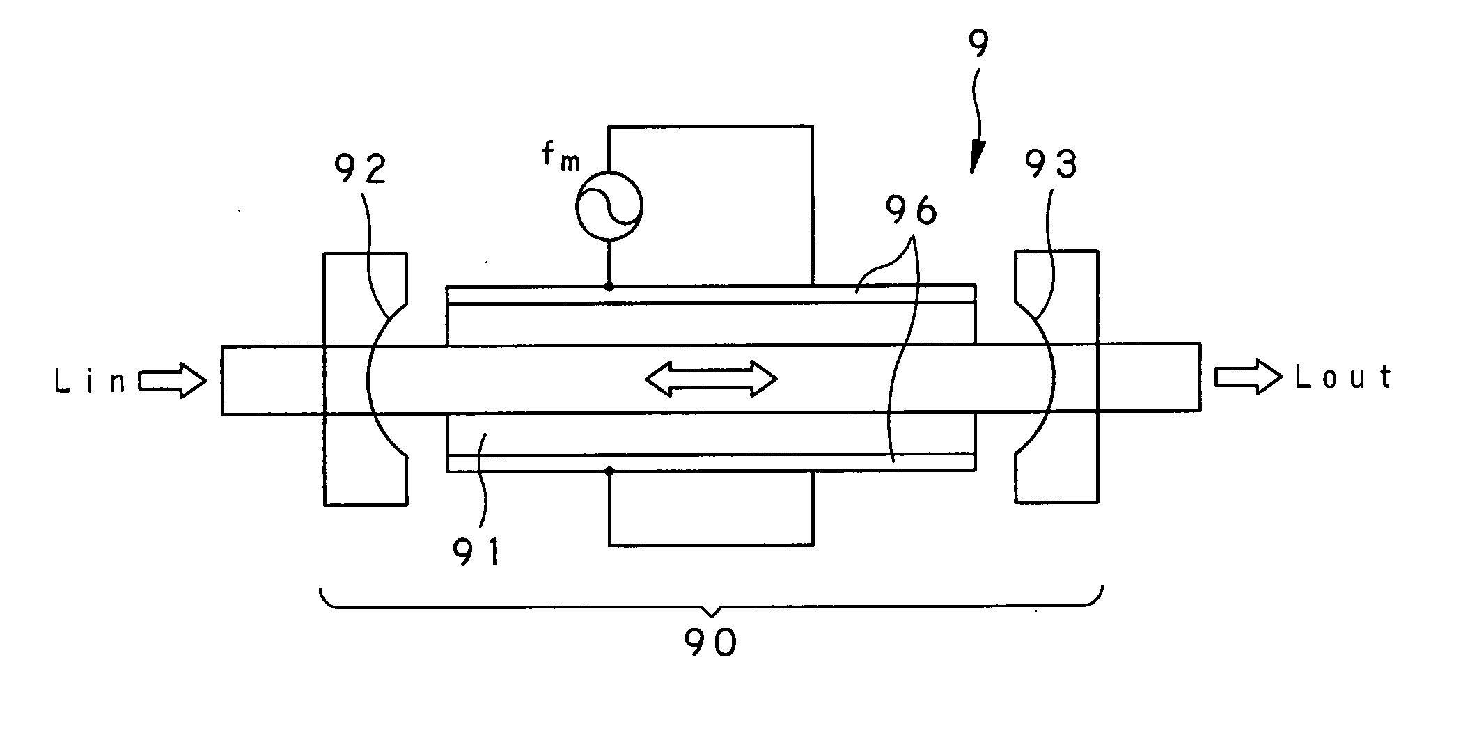
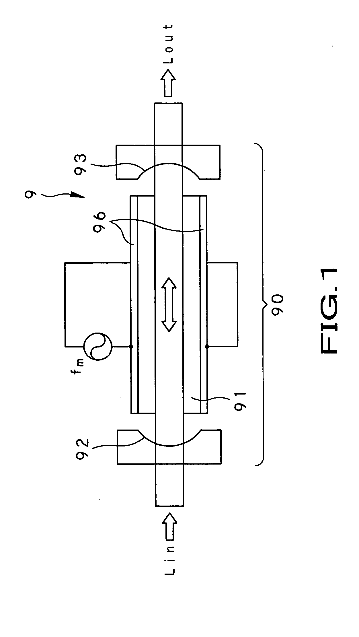
FIG. 3 shows an instance of application of the optical frequency comb generator of the present invention to a bulk type optical frequency comb generator 10. This bulk type optical frequency comb generator 10 includes an optical phase modulator 111, an optical resonator 110, composed of an incident side reflecting mirror 112 and an outgoing side reflecting mirror 113, mounted facing each other with the optical phase modulator 111 in-between, an electrode 116 and an oscillator 117.

The optical resonator 110 causes light resonation of light Lin, incident via incident side reflecting mirror 112, in a space between the incident side reflecting mirror 112 and the outgoing side reflecting mirror 113, to radiate a portion Lout of the incident light through the outgoing side reflecting mirror 113.

The optical phase modulator 111 is an optical device, formed of a bulk crystal e.g. of lithium ...


PUM

PropertyMeasurementUnit
frequencyaaaaaaaaaa
reflectanceaaaaaaaaaa

Abstract

An optical frequency comb generator includes an oscillator (117) for oscillating modulating signals of a preset frequency, and an optical resonator (110) formed by an incident side reflecting mirror (112) and an outgoing side reflecting mirror (113), arranged parallel to each other. The optical resonator causes resonation in light incident via the incident side reflecting mirror (112). The optical frequency comb generator also includes an optical phase modulation unit (111) arranged between the incident side reflecting mirror (112) and the outgoing side reflecting mirror (113) for phase modulating the light, resonated by the optical resonator (110), by the modulating signals supplied from the oscillator (117), and for generating a plurality of sidebands centered about the frequency of the incident light at a frequency interval of the modulating signal. The outgoing side reflecting mirror (113) sets the transmittance from one frequency to another responsive to the light intensity of the generated sidebands.

Description

TECHNICAL FIELD This invention relates to an optical frequency comb generator that may be applied in a field which is in need of a standard light source of multi-wavelength highly coherent light, or a light source that is able to exploit the coherence between different wavelengths, such as in optical communication, optical CT or an optical frequency standard. BACKGROUND ART If, in heterodyne detection, the light frequency is to be measured to a high frequency, the light to be measured is caused to interfere with other light and an electrical signal of the optical beat frequency generated is detected. The bandwidth of laser light that may be measured in this heterodyne detection is limited to the band of the light receiving element used in the detection system, and is generally on the order of tens of GHz. On the other hand, the bandwidth of light that may be measured needs to be increased further in order to measure the frequency of absorption lines, distributed over a wide range...

Claims


Application Information

Patent Timeline
Patent Type & Authority Applications(United States)
IPC IPC(8): G02F1/21G02F2/02H01S3/00
CPCG02F1/21G02F2203/56G02F2/02
Inventor KOUROGI, MOTONOBUBAMBANG, WIDIYATMOKONAKAMOTO, OSAMUMISAWA, SHIGEYOSHINAKAYAMA, YOSHINOBU
Owner JAPAN SCI & TECH CORP
Why Eureka
Try Eureka