Optically driven audio system

an audio system and opto-driven technology, applied in the direction of optical signal transducers, transducer details, mouthpiece/microphone attachments, etc., can solve the problems of electromagnetic interference, subject to interference, prior systems tend to suffer from certain disadvantages, etc., to achieve effective delivery over the free space, add noise protection, and high noise environment

Inactive Publication Date: 2005-01-27
BUCHHOLZ JEFFREY C
View PDF10 Cites 83 Cited by
  • Summary
  • Abstract
  • Description
  • Claims
  • Application Information

AI Technical Summary

Benefits of technology

[0007] The audio system of the present invention includes an earplug which may include sound delivery and/or sound capture features as discussed above, and an earmuff is worn over the earplug to provide added noise protection in a high noise environment. The need for wire connections between the earmuff and earplug, and for onboard power sources in the earplug (i.e., batteries), may be avoided by providing both sound signals and power between the earplug and earmuff over a free space optical link: sound-encoded light signals may be delivered by light sources situated on the earplug and/or earmuff, and may be received by the other component by appropriate photoreceivers and then converted back into sound, if desired. Addi

Problems solved by technology

However, the prior systems tend to suffer from certain disadvantages.
Where they receive and/or send sound signals via wire, they can be subject to electromagnetic interference, and they tend to “tether” the wearer to a fixed location.
Where wi

Method used


Image

  • Optically driven audio system
  • Optically driven audio system

Examples


Embodiment Construction

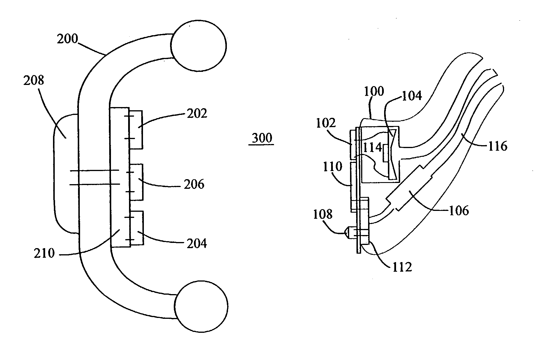
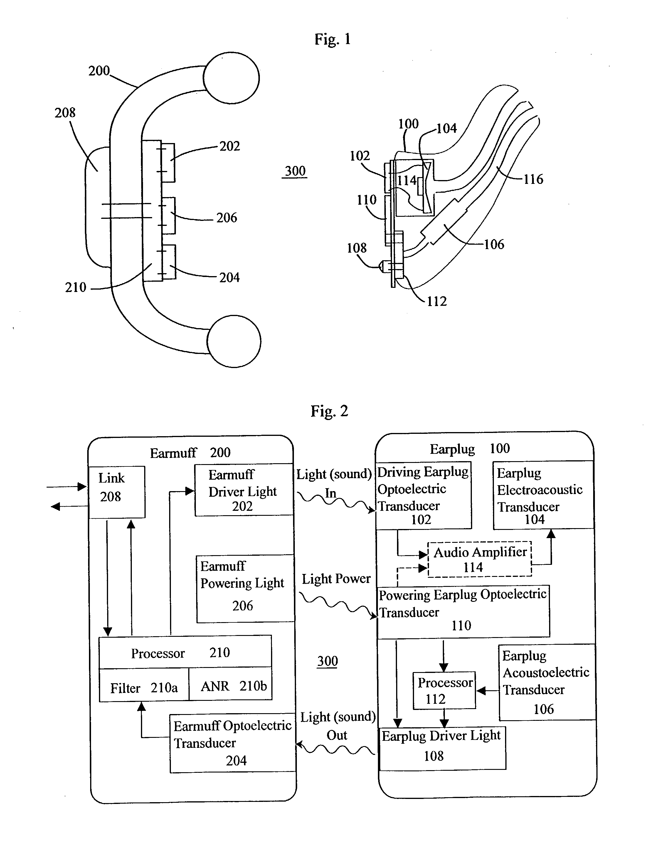
[0011] An exemplary version of the invention is illustrated in FIGS. 1 and 2, wherein an audio system includes an earplug 100 and an earmuff 200, wherein the earplug 100 receives sound signals from (and / or sends sound signals to) the earmuff 200 across a free space 300. The earplug 100 may be adapted for mounting within an ear (as depicted in FIG. 1) or on an ear (as by including an over-the-ear hook), and the earmuff preferably has an earmuff interior sized to fit over the ear which bears the earplug 100. The lack of any physical connection between the earmuff 200 and earplug 100 across the free space 300 allows the earmuff 200 to provide passive noise reduction—it reduces the ambient noise received by the ear canal (such reduction also being assisted by the earplug 100)—while preventing direct conduction of ambient sound vibration between the earmuff 200 and earplug 100. The presence of the free space 300 also allows easy “don-and-doff,” whereby a user may wear the earplug 100 whi...


PUM


Abstract

An audio system includes an earplug with a speaker to deliver sound to the ear, and/or a microphone which captures sound in the ear canal, and an earmuff is worn over the earplug. The earplug receives sound signals from the earmuff (and/or transmits captured sound signals to the earmuff) by translating such sound signals into light signals which are transmitted over a free space situated between the earmuff and earplug. The light signals are then received at the earplug and/or earmuff and converted to electrical signals which may be further transmitted (e.g., from the earmuff to some external communications device) or converted to sound (e.g., in the earplug by having the electrical signals drive an earplug speaker). If power is required by the earplug, the need for on-board power sources may be avoided by converting light transmitted from the earmuff into power at the earplug. Electrical shock and physical snag hazards are avoided, and the earmuff is easily put on and removed, owing to the lack of wires or other physical connections between the earplug and earmuff. Additionally, by avoiding wires or radio transmission between the earplug and earmuff, electromagnetic interference may be reduced.

Description

CROSS-REFERENCE TO RELATED APPLICATIONS [0001] This application claims priority under 35 USC §119(e) to U.S. Provisional Patent Application 60 / 368,467 filed 27 Mar. 2002, the entirety of which is incorporated by reference herein.STATEMENT REGARDING FEDERALLY SPONSORED RESEARCH [0002] This invention was made with United States government support awarded by the United States Navy (Naval Air Warfare Center Aircraft Division), Contract No. N68335-02-C-3040. The United States has certain rights in this invention.FIELD OF THE INVENTION [0003] This disclosure concerns an invention relating generally to personal audio equipment, and more specifically to headsets, earplugs, and similar personal audio listening equipment. BACKGROUND OF THE INVENTION [0004] In high noise environments, in-the-ear active earplugs—wherein speakers deliver sound directly to the ear canal—help improve signal to noise, and thus the intelligibility of transmitted music or speech. The earplug serves as a passive atten...

Claims


Application Information

Patent Timeline
IPC IPC(8): H04R1/08H04R1/10H04R23/00
CPCH04R1/083H04R23/008H04R1/1016H04R1/1083
Inventor BUCHHOLZ, JEFFREY C.
Owner BUCHHOLZ JEFFREY C
Why Eureka
Try Eureka