
Rotating chip removing tool, such as a drilling and chamfering tool, with cutting inserts, and a milling cutter with cutting inserts

Inactive Publication Date: 2005-01-27
KENNAMETAL INC
View PDF19 Cites 13 Cited by
  • Summary
  • Abstract
  • Description
  • Claims
  • Application Information

AI Technical Summary

Benefits of technology

While the active cutting edge that is adjacent to the first flank is provided for machining that requires chip removal, in one possible realization, the other, second flank can be supported on a support surface of the tool body that is provided for that purpose. In addition to the guide web on the plate seat, there also can be an additional element that holds the cutting plate in the specified position and further improves the retention of the cutting plate in the desired position. The support surface thereby can be realized so that the cutting plate extends with its second flank partly around to the back of the tool body and grips it from behind, i.e. the cutting plate cannot be removed from the plate seat in a direction of movement which is exclusively perpendicular to the plate seat. This arrangement achieves a particularly accurate and secure guidance of the cutting plate on the tool body.
The second support of the cutting insert, which acts on the rear side of the cutting insert, can be effected by means of a bearing face arranged below the cutting edge in the area of the flank of the cutting insert. This bearing face can form an acute angle with the support face. The main components of the reaction forces during clamping and cutting are directed, due to this feature, to the above-explained bearing vee and thus promote a stable and safe cutting process. In this way, as a whole, an insert seat statically defined in itself is formed, which does not require any additional bearing face located on the drill. Consequently, this enables a modular construction of the chamfering collar or ring, which can be divided into chamfering cutting inserts and a carrier ring. The advantage of this embodiment lies in the higher flexibility of application. It is possible, for example, to fix different chamfering cutting inserts on one carrier or to exchange worn cutting inserts. Another advantage is the fact that one cutting insert type can be used for different chamfering diameters, which results in savings regarding inventory, number of types, and higher batch sizes in production.

Problems solved by technology

This counterbore, however, has the disadvantage, among other things, that the diameter of the cutting plate must be greater than the diameter of the boring in which the counterbore is producing a bevel.
On the other hand, no means are provided to guarantee that the cutting insert itself will be held in position with the total absence of play or backlash.
However, the adjustability of the cutting plates also requires a complex and expensive design and limits the stability of the cutting plate mounting.

Method used


Image

  • Rotating chip removing tool, such as a drilling and chamfering tool, with cutting inserts, and a milling cutter with cutting inserts
  • Rotating chip removing tool, such as a drilling and chamfering tool, with cutting inserts, and a milling cutter with cutting inserts
  • Rotating chip removing tool, such as a drilling and chamfering tool, with cutting inserts, and a milling cutter with cutting inserts

Examples


Embodiment Construction

Parts that are identical in all the figures are identified by the same reference numbers.

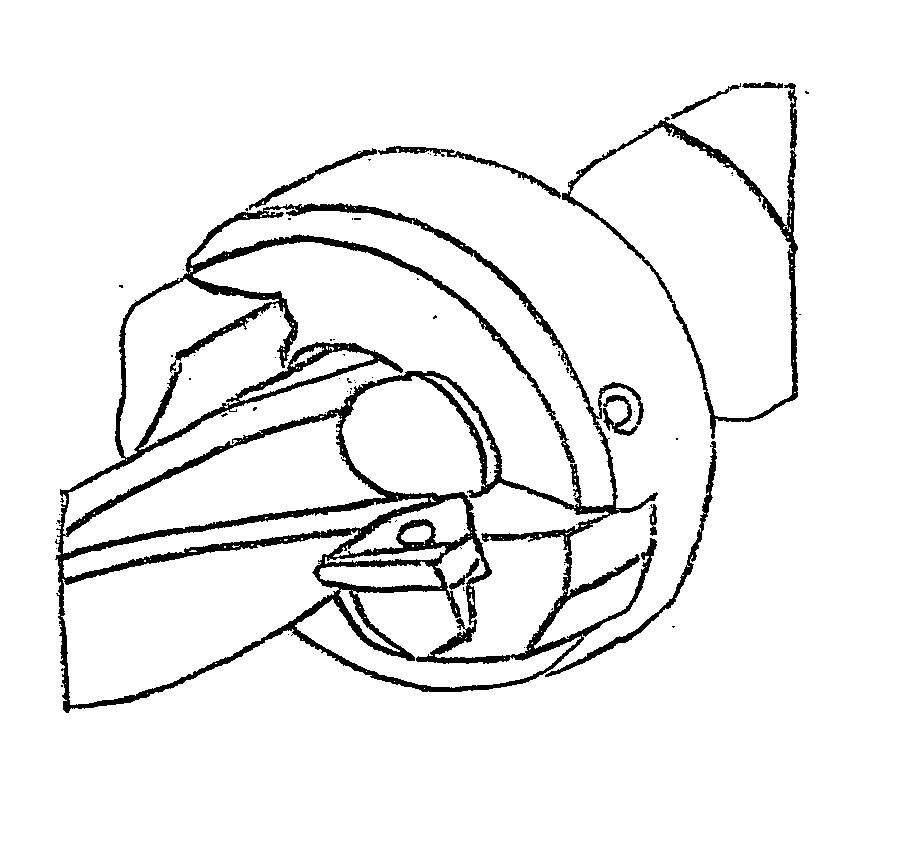
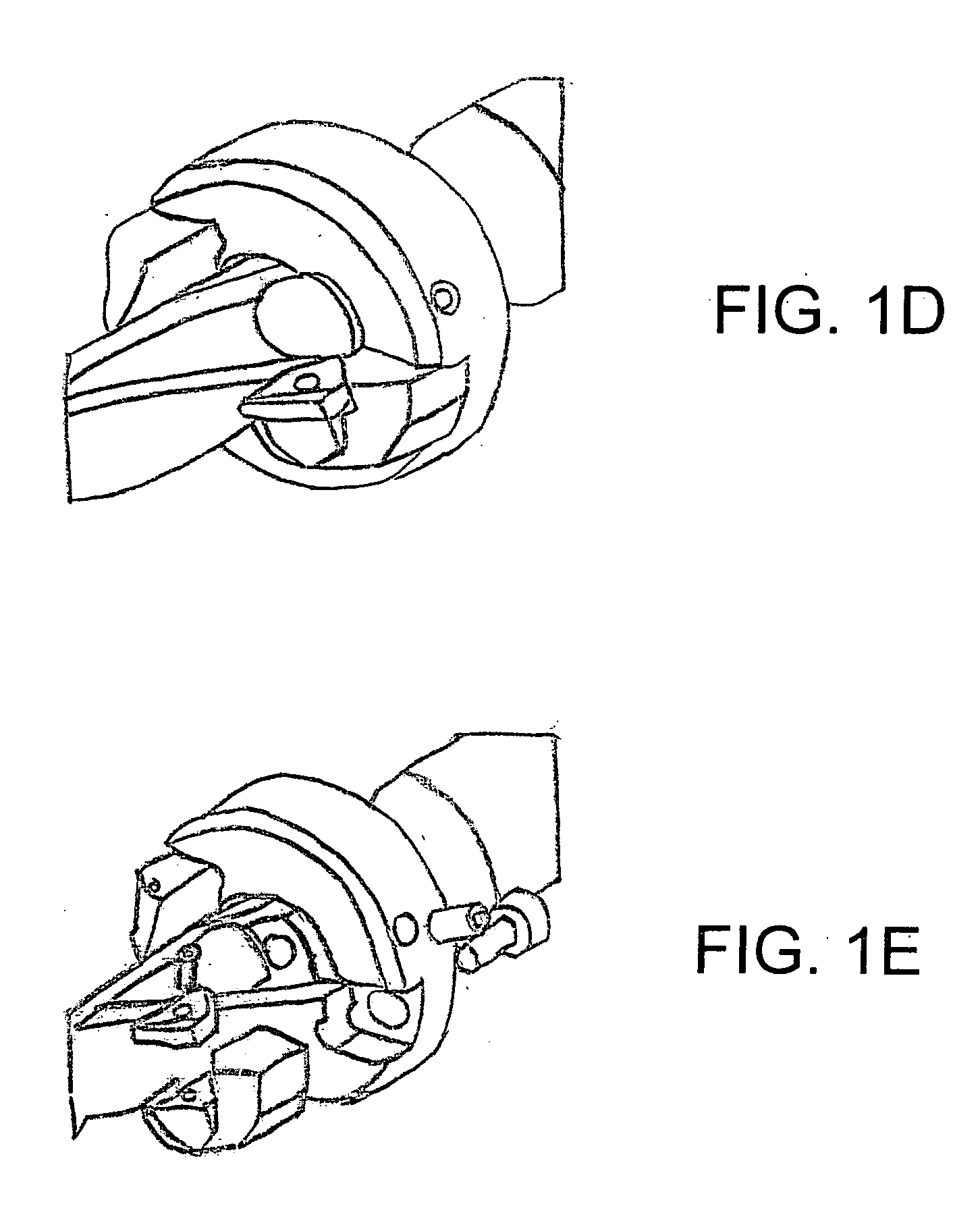
FIG. 1D shows a drilling and chamfering arrangement according to one possible embodiment. FIG. 1E shows an exploded view of the drilling and chamfering arrangement shown in FIG. 1D according to one possible embodiment. In this embodiment, a chamfering collar or ring with two cutting inserts is removably attached to a drill. During operation, the drill initially drills a hole in a workpiece and moves into the workpiece so that the cutting inserts countersink the opening of the hole.

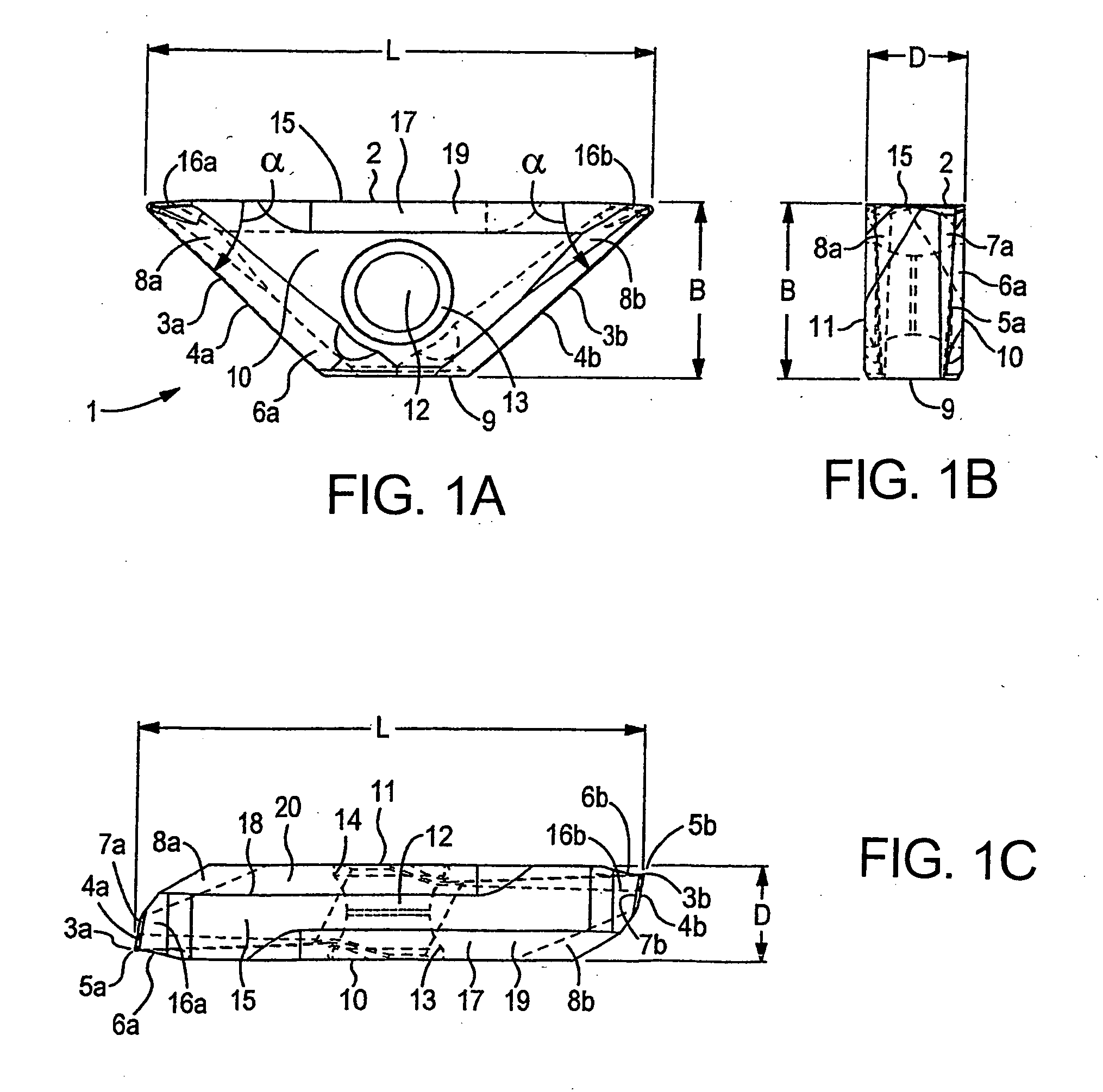
FIGS. 1A to 1C show a number of different views of a trapezoidal cutting plate, which is designated the indexable insert 1 below with a trapezoidal base line 2 having length L and two trapezoidal limbs 3a, 3b, which each enclose an angle a of approximately 45° with the trapezoidal base line 2. On the trapezoidal limbs 3a, 3b, the trapezoidal indexable insert 1 has respective flanks 4a, 4b and cutting edges 5a, 5b. D...


PUM

PropertyMeasurementUnit
Lengthaaaaaaaaaa
Thicknessaaaaaaaaaa
Widthaaaaaaaaaa

Abstract

A rotating chip removing tool, such as a drilling and chamfering tool, and a milling cutter, each of which have at least one cutting insert or cutting plate. The cutting plate has a guide recess that adjoins the underside of the cutting plate. A plate seat for accommodating the cutting plate is provided on a tool body of the chip removing tool and has a guide fillet or surface which corresponds to the guide recess.

Description

BACKGROUND 1. Technical Field This application relates to a rotating chip removing tool with a cutting plate and a tool body, in particular a counterbore or milling cutter. 2. Background Information For machining that involves chip removal, in particular for metal cutting, a rotating chip removing tool with a cutting plate, in particular an indexable insert, is frequently used. The indexable insert can be fixed to the tool holder in different positions and thus makes it possible to use different cutting edges or different areas of a cutting edge, which increases the useful life of the cutting plate. The indexable insert or another type of cutting plate can be affixed to a tool body, generally in a clearly defined position. DE 92 011 13 U1, for example, describes a round cutting plate that is held on the tool body in a form-fitting manner. For this purpose, both the cutting plate and the tool body have moldings and recesses that are engaged with one another in a form-fitting con...

Claims


Application Information

Patent Timeline
IPC IPC(8): B23B27/16B23B51/00B23B51/04B23B51/10B23C5/22
CPCB23B51/108B23B2251/50B23C5/2213B23C2200/0416Y10T408/8725B23C2200/165B23C2200/326Y10T408/86B23C2200/0472
Inventor JAGER, HORST
Owner KENNAMETAL INC
Features
  • Generate Ideas
  • Intellectual Property
  • Life Sciences
  • Materials
  • Tech Scout
  • Unparalleled Data Quality
  • Higher Quality Content
  • 60% Fewer Hallucinations
Learn More