Socket for electronic part

a technology for electronic parts and sockets, which is applied in the direction of coupling contact parts, fixed connections, coupling device connections, etc., can solve the problems of inferior workability and assemblability of contact parts, comparatively high cost, and unsatisfactory sockets for electronic parts having such a construction, so as to achieve sharp enhancement of workability and assemblability of electrode portions, and reduce cost. the effect of comparatively low cos

Inactive Publication Date: 2005-01-27
TNG CORP LTD
View PDF7 Cites 12 Cited by
  • Summary
  • Abstract
  • Description
  • Claims
  • Application Information

AI Technical Summary

Benefits of technology

[0017] According to the socket of the present invention for use with an electronic part, each electrode portion is constructed of a single piece and is structurally simplified, so that the workability and assemblability of the electrode portion can be sharply enhanced, and the cost thereof becomes comparatively low. Moreover, the electrical contact portion between each first contact and the corresponding electrode terminal of the electronic part (or a printed circuit board) exists at an oblique upper position as viewed from the electrical contact portion between each second contact and the corresponding electrode terminal of the printed circuit board (or the electronic part), so that the dimension of a leaf spring portion in the lengthwise direction thereof can be set large. In turn, even when the thickness of a socket body itself is small, each electrode terminal of the electronic part and the corresponding electrode terminal of the printed circuit board can be reliably brought into electrical contact, and a stable contact resistance can be attained.

Problems solved by technology

The socket for the electronic part having such a construction, however, has been still unsatisfactory as stated below.
Besides, the contact parts have complicated shapes, and the two pieces of parts are required, so that the workability and assemblability of the contact parts are inferior, and the cost thereof is comparatively high.

Method used

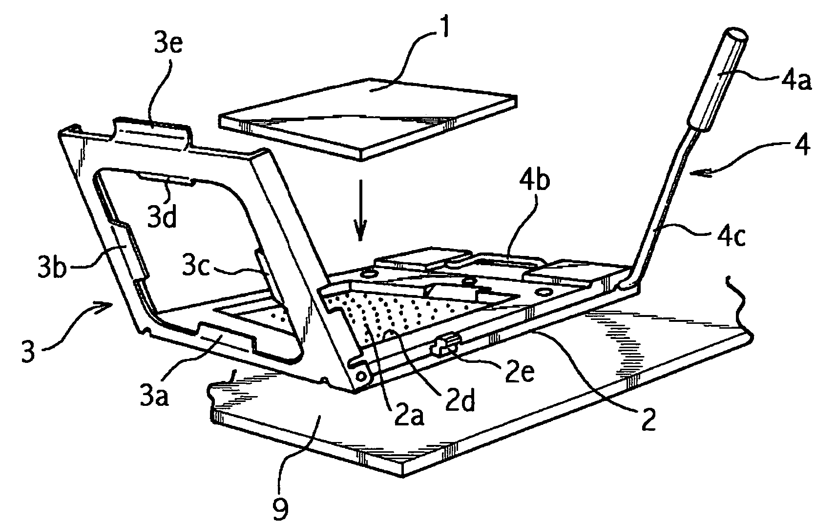
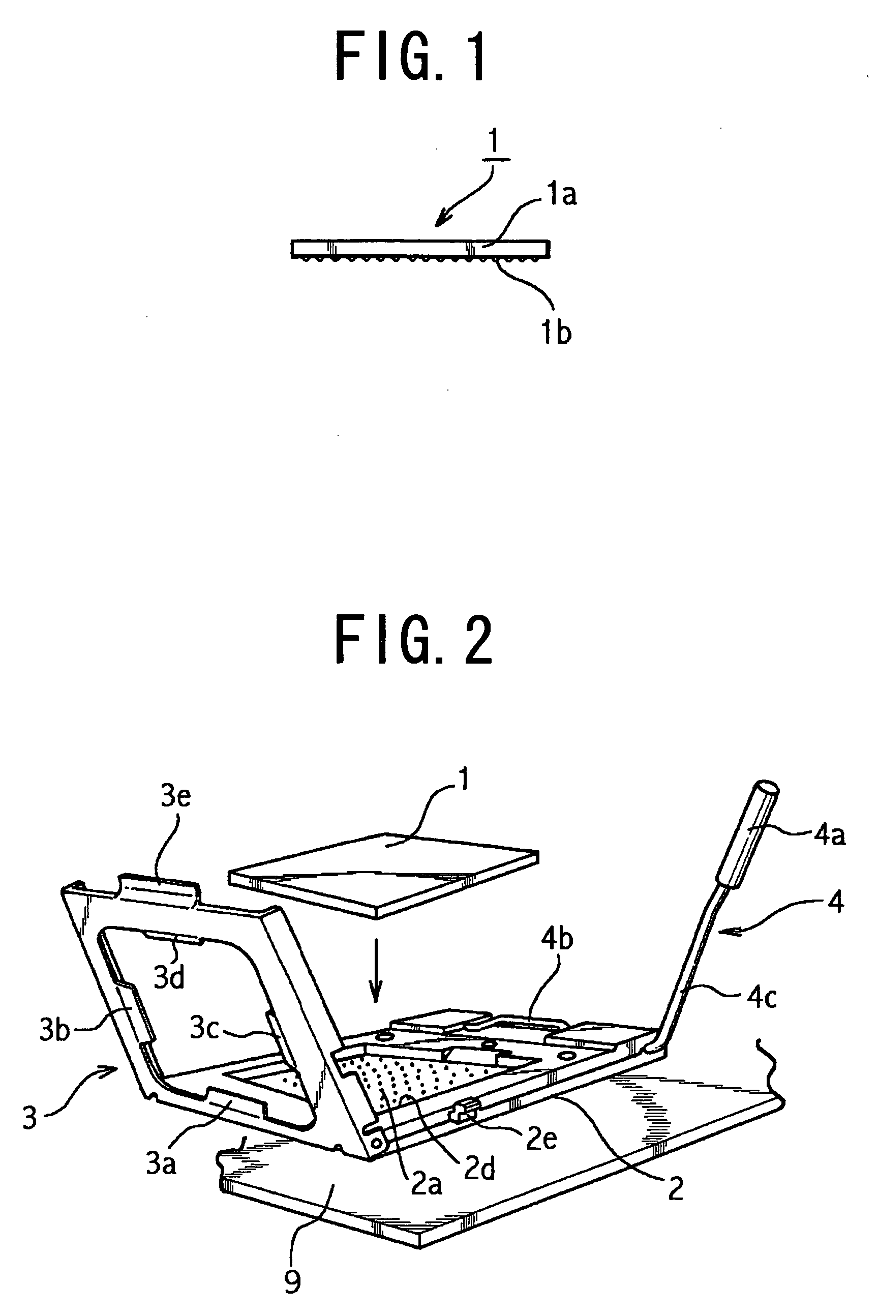
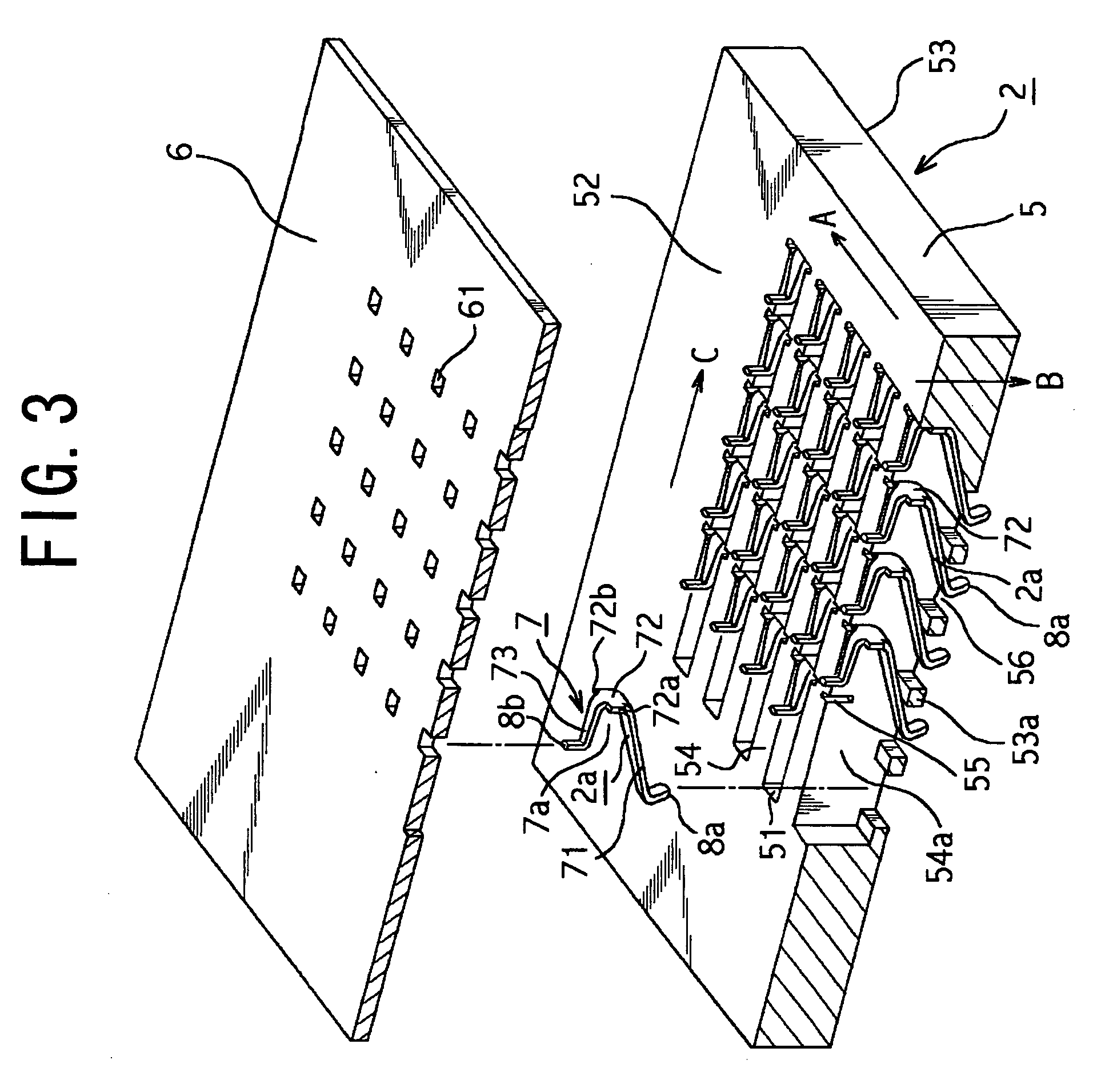

Image

  • Socket for electronic part
  • Socket for electronic part
  • Socket for electronic part

Examples


first embodiment

[0046] Here in the first embodiment, as shown in FIG. 6, the lengthwise dimension L1 of the obliquely extending portion 73 constituting the electrode portion 2a is set to be nearly double the lengthwise dimension L2 of the horizontally extending portion 71. Thus, as will be stated later, the electrical contact (hereinbelow, termed “first electrical contact portion”) P1 between the first contact 8a and the electrode terminal 1b of the electronic part 1 exists at an oblique upper position as viewed from the electrical contact (hereinbelow, termed “second electrical contact portion”) P2 between the second contact 8b and the electrode terminal 9a of the printed circuit board 9. That is, a vertical line V1 which passes through the first electrical contact portion P1 exists at a position spaced a predetermined length L3 (about 0.5 mm) in the lengthwise direction C from a vertical line V2 which passes through the second electrical contact portion P2.

[0047] Next, a method for electrically c...

second embodiment

[0053] In the second embodiment, hole surrounding portions 53b each having a taper T as shown in FIG. 9 are formed instead of the hole surrounding portions 53a of the flat plate member 5 as shown in FIG. 3, and an electrode portion 2b shown in FIG. 10 is used instead of the electrode portion 2a shown in FIG. 4.

[0054] In the second embodiment, as shown in FIG. 9, that corner of the hole surrounding portion 53b of the flat plate member 5 which opposes to the obliquely extending portion 73 of the electrode portion 2b is formed with the taper T which rises up obliquely from the left side toward the right side as viewed in the figure. Besides, the opposing sidewalls 54a of each recess 51 of the flat member 5 are formed with bearings 55b which are constructed similarly to the pairs of first engagement grooves 55 (refer to FIG. 3) stated before. Further, shafts 74a and 74b each of which has a diameter somewhat smaller than the groove width of the bearing 55b are unitarily provided at both ...

third embodiment

[0059] Referring to FIG. 12, in the third embodiment, hole surrounding portions 53b each having a taper T as are similar to the hole surrounding portions 53b of the flat plate member 5 shown in FIG. 9 are formed, and an electrode portion 2c shown in FIG. 13 is used instead of the electrode portion 2a shown in FIG. 4.

[0060] In the third embodiment, as shown in FIG. 12, the opposing sidewalls 54a of each recess 51 of the flat plate member 5 are formed with pairs of engagement grooves (hereinbelow, termed “second engagement grooves”) 55c each of which is longer than the first engagement groove 55 (refer to FIG. 3) (each of which is nearly equal to the depthwise dimension of the recess 51). Besides, as shown in FIG. 13, both the side parts of the coupling portion 72 of a leaf spring portion 7 constituting the electrode portion 2c are provided with extension pieces 75a and 75b which are formed unitarily with the coupling portion 72 toward the sides of the sidewalls 54a of each recess 51,...


PUM


Abstract

In a socket for an electronic part, each electrode portion includes a leaf spring portion which is disposed by bending a conductive plate material substantially into a U-shape and facing an opening part in a direction substantially perpendicular to the thickness direction of a socket body, a first contact which is unitarily provided at one free end of the leaf spring portion and which is held in electrical contact with the corresponding electrode terminal of the electronic part, and a second contact which is unitarily provided at the other free end of the leaf spring portion and which is held in electrical contact with the corresponding electrode terminal of a printed circuit board. The leaf spring portion includes a horizontally extending portion which is arranged substantially in parallel with the horizontal surface of the printed circuit board, a coupling portion which is unitarily provided at one end part of the horizontally extending portion in the thickness direction of the socket body, and an obliquely extending portion which is unitarily provided at the end part of the coupling portion so as to oppose to the horizontally extending portion and to obliquely rise up toward the electronic part. Engagement pieces which are held in engagement with engagement grooves provided in partition walls are formed on both the sides of the coupling portion unitarily with this coupling portion.

Description

BACKGROUND OF THE INVENTION [0001] 1. Field of the Invention [0002] The present invention relates to a socket for an electronic part. More particularly, it relates to a socket which is so designed that, when the electronic part of a CPU, an MPU or the like is pushed against a socket body, the electrode terminals of the electronic part and those of a printed circuit board can be electrically connected through electrode portions disposed in the socket body. [0003] 2. Description of the Related Art [0004] A known socket of this kind for an electronic part is so constructed that, when the electronic part is pushed against a socket body, the electrical contact between the electrode terminals of the electronic part and the electrode portions of the socket body is maintained, while the electrode portions of the socket body are connected to the electrode terminals of a printed circuit board (refer to, for example, U.S. Pat. No. 6,004,141). [0005] With the socket for the electronic part, a p...

Claims


Application Information

Patent Timeline
Patent Type & Authority Applications(United States)
IPC IPC(8): H01L23/32H01R13/11H01R13/24H01R13/428H01R33/76
CPCH01R13/2435H01R9/096H01R12/52
Inventor MOTOHASHI, SENTARO
Owner TNG CORP LTD
Why Eureka
Try Eureka