
Lie-down massager

a massager and lie-down technology, applied in the field of lying-down massagers, can solve the problems of the spring mechanism being too soft to push up the massaging bumps, and achieve the effect of improving the therapeutic

Inactive Publication Date: 2005-01-27
SHIM 30 SIMON K
View PDF34 Cites 46 Cited by
  • Summary
  • Abstract
  • Description
  • Claims
  • Application Information

AI Technical Summary

Benefits of technology

"The present invention is a lie-down massager that improves therapeutic effects by harmonizing a vertical reciprocation with a widthwise reciprocation of massage bumps. The massager includes a base frame with an elongated top panel with an elongated top opening, a rider, and a lifter. The massage bumps are fixed downwardly to the lifter, and first and second supports are horizontally aligned along a top portion of the massage member. The massager also includes a gear shaft and a gear-motor application or a cam-motor application to control the rotation of the gear shaft. The massage bumps are formed in hemisphere and each pair of bumps is aligned parallel to the direction of the rider's movement. The massager optimally combines a lengthwise reciprocation of massage bumps with a vertical and widthwise reciprocation of the massage bumps for an evenly widespread massaging on the back and neck of a patient. The combination of triple reciprocations results in a virtually total back massaging while relaxing on the bed or mat type massager. The massager maximally synthesizes multiple reciprocations in the movement of the massage bumps while relaxing on the bed or mat type massager, thereby enhancing product reliability and customer satisfaction."

Problems solved by technology

However, when it comes to therapeutic effects, the spring mechanism proves too soft to push up the massaging bumps when stronger pressure is required, because tension of springs applies equally to patients lying on the massaging device regardless of patient's requirements.

Method used


Image

  • Lie-down massager
  • Lie-down massager
  • Lie-down massager

Examples


Embodiment Construction

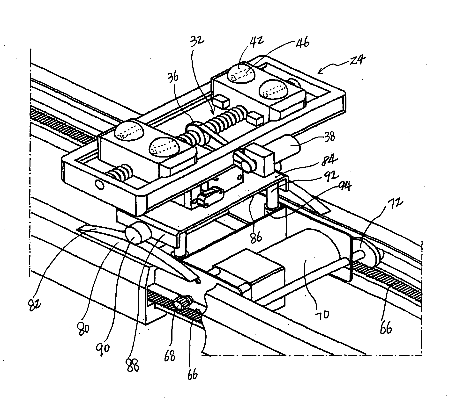
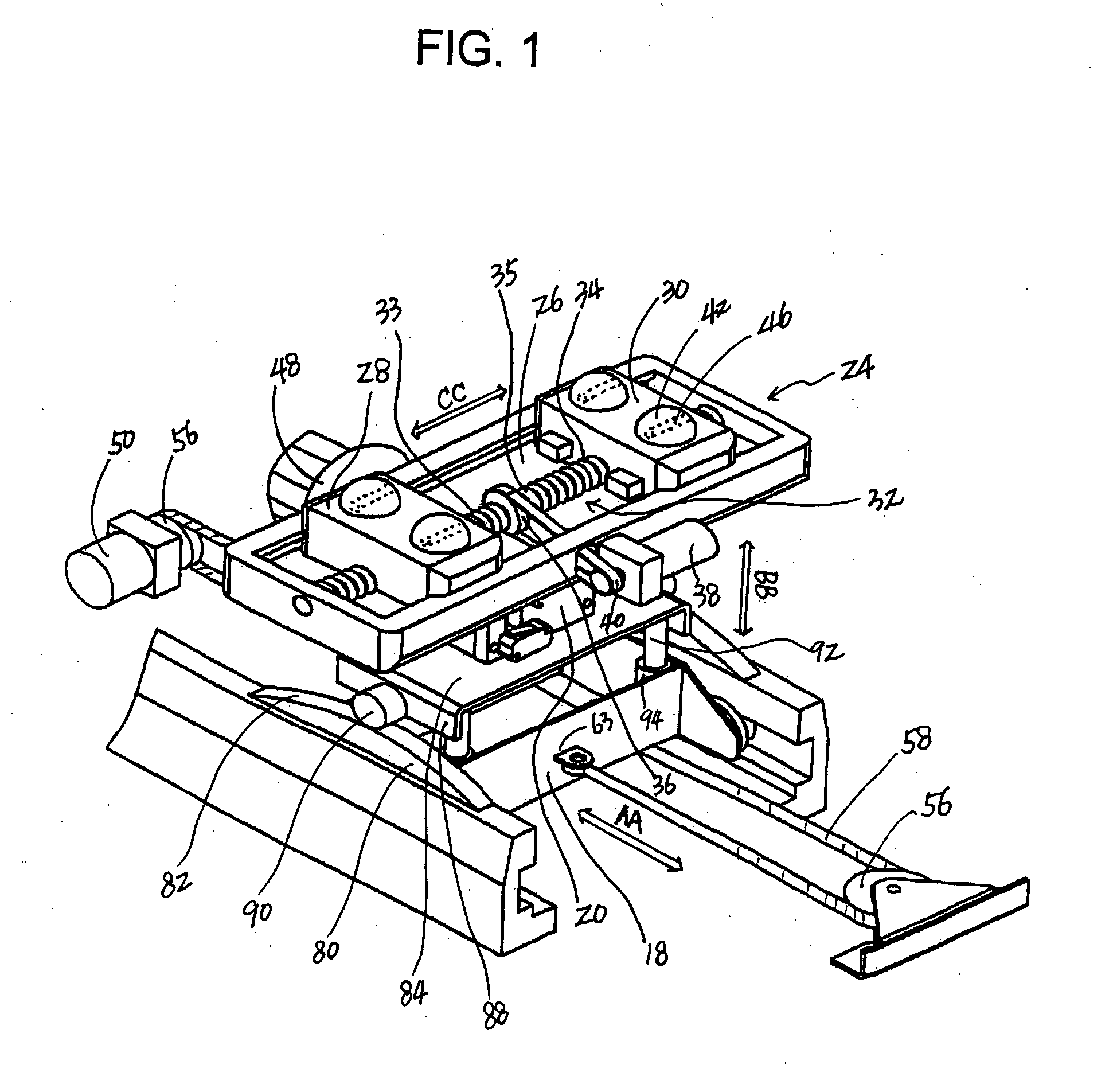
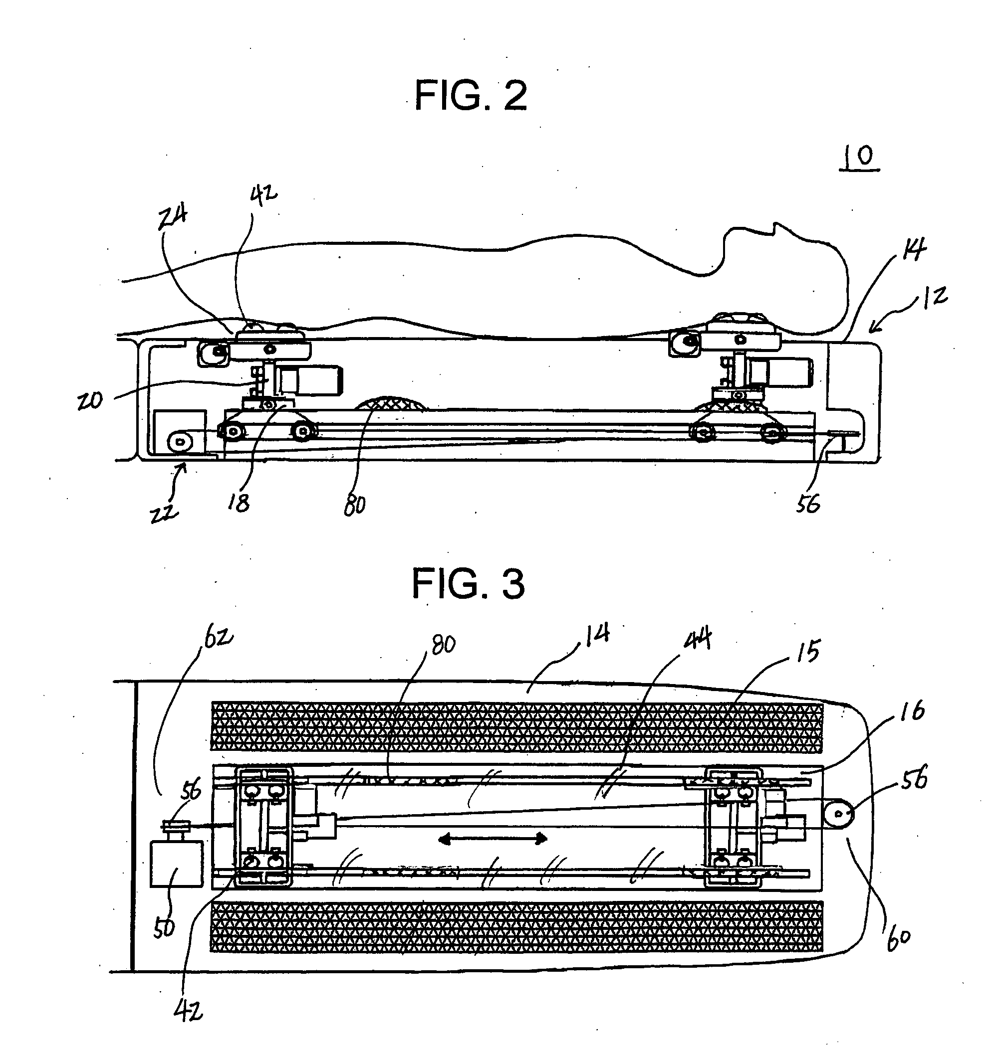
[0022]FIG. 1 shows a brief construction of a lie-down massager 10 according to a preferred embodiment of the present invention. FIG. 2 shows the lie-down massager 10 with a patient lying thereon, and FIG. 3 shows a plan view of the massager 10 excluding the patient. As shown therein, the lie-down massager 10 includes a base frame 12 in a bed type or a mat type. The base frame 12 includes an elongated top panel 14 with a heating member 15 spread in the top panel 14 to further comfort the patient on the massager 10. An elongated opening 16 is formed centrally and lengthwisely through the elongated top panel 14. The heating member 15 is preferably formed around the elongated opening 16 to generate heat rays at a predetermined temperature. The massager 10 includes a rider 18 and a lifter 20. The lifter 20 is liftedly engaged to the rider 18 to make a vertically reciprocal movement relative to the rider. The rider 18 is provided below the elongated top panel 14 of the base frame 12 to ma...


PUM


Abstract

A lie-down massager comprises a base frame having a top panel with a top opening formed centrally and lengthwisely through the top panel, a rider provided below the top panel to make a horizontally reciprocal movement relative to the base frame, a lifter liftedly engaged to the rider to make a vertically reciprocal movement relative to the rider, a massage member fixed downwardly to the lifter with supports horizontally aligned along a top portion of the massage member, massage bumps attached atop the first and second supports, and a pad covering the massage bumps and the elongated opening of the base frame. The supports repeatedly approach to and distance from each other within the top opening.

Description

BACKGROUND OF THE INVENTION [0001] The invention relates generally to a massaging device. More particularly, the present invention relates to an improved lie-down massager capable of efficiently treating bodily malfunctions such as back pain and gastrointestinal weakness by applying a therapeutic massaging treatment along the back and neck of a patient lying down on the massager whose massaging bumps move horizontally and vertically along the patient's spinal cord and neck in which the vertical movement of the massaging bumps optimally coordinates with a widthwise reciprocation to repeatedly approach to and distance from each other. [0002] Conventional bed or mat type massaging devices employ a spring mechanism for vertically moving massaging bumps. As disclosed U.S. Pat. No. 6,454,732, a spring mechanism allows the massaging bumps to gently move up and down. However, when it comes to therapeutic effects, the spring mechanism proves too soft to push up the massaging bumps when stron...

Claims


Application Information

Patent Timeline
Patent Type & Authority Applications(United States)
IPC IPC(8): A61H1/00A61H7/00A61H37/00
CPCA61H7/004A61H2201/0138A61H2201/0142A61H2201/0207A61N2005/0659A61H2201/10A61H2201/1669A61H2205/04A61H2205/081A61H2201/0228
Inventor KIM, HAKJIN
Owner SHIM 30 SIMON K
Learn More