Input/output control apparatus
- Summary
- Abstract
- Description
- Claims
- Application Information
AI Technical Summary
Benefits of technology
Problems solved by technology
Method used
Image
Examples
configuration example 1
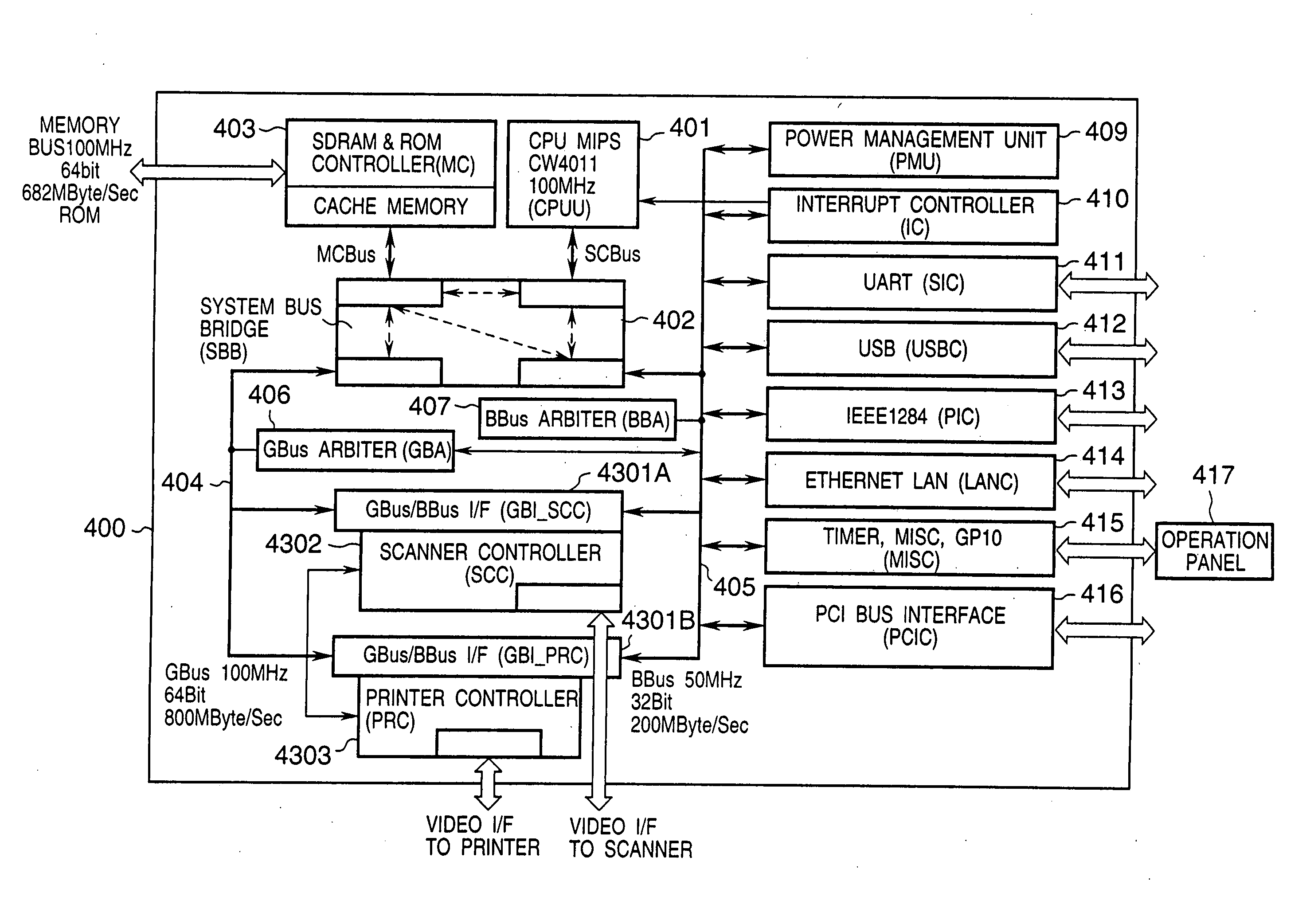
In this example, power management is carried out by turning on and off a clock to an internal logic and power consumption can be set at only two levels. One of these levels is sent as a status signal to the power management unit 409. FIG. 88 shows a block diagram of a bus agent. A bus agent 5501 comprises an internal logic 5502 for each unit, a decoder 5503 which decodes an address, a clock control section 5504 and a clock gate 5505. The decoder 5503 and the clock control section 5504 which are always operating monitor bus activity monitoring and perform gating of the clock into the internal logic as power management control.
<Clock Control> The bus agent detects the bus activity and automatically turns on / off the clock. The bus agent has three states of sleep, wake up and wait. In the sleep state, the bus agent has no activity and the clock gate clock is stopped. Even in the sleep state, the decoder 5503 and the clock control section 5504 are operating to monitor the bus...
second embodiment
[Second Embodiment]
The second embodiment of the present invention will be described.
In the first embodiment, the parallel operation statuses of functions selected by the user for use and remaining functions unselected not to be executed are recognized by the user on the operation window 2 from the icons 5, 12, 18, and 24 representing the selected functions, the icons 4, 11, 17, and 23 representing the operation statuses of unselected functions, and the messages 3, 10, 16, and 22. In the second embodiment, operation window areas prepared for respective functions are hierarchically displayed to present the icons and messages of the respective functions, thereby making the user recognize the parallel operation statuses of functions selected by the user for use and remaining functions unselected not to be executed.
FIG. 115 is a plan view showing an operation panel 1 when the copying function is selected in the second embodiment. FIGS. 116 through 118 are plan views each showing an o...
third embodiment
[Third Embodiment]
The third embodiment of the present invention will be described.
In a conventional composite image forming apparatus, the user recognizes switching of a function by turning on / off an LED indicator lamp arranged in correspondence with the character display of each function on the operation panel.
According to this method, however, the user is difficult to recognize the switching. The user must carefully confirm the switching status, which takes a long time.
If the switched function is an erroneously selected one, the user takes a long time to confirm and judge this. That is, the user cannot easily judge whether a function the user wants to use is selected, or a function is erroneously selected and must be switched again. This is a burden to the user.
To solve this, the third embodiment allows the user to recognize and judge a switched function immediately upon switching the function in a composite image forming apparatus.
More specifically, in the third and fo...
PUM
 Abstract
Description
Claims
Application Information
 - R&D
- Intellectual Property
- Life Sciences
- Materials
- Tech Scout
- Unparalleled Data Quality
- Higher Quality Content
- 60% Fewer Hallucinations
Browse by: Latest US Patents, China's latest patents, Technical Efficacy Thesaurus, Application Domain, Technology Topic, Popular Technical Reports.
© 2025 PatSnap. All rights reserved.Legal|Privacy policy|Modern Slavery Act Transparency Statement|Sitemap|About US| Contact US: help@patsnap.com


