Method for manufacturing float valve apparatus

Inactive Publication Date: 2005-02-03
PIOLAX CO LTD
View PDF3 Cites 8 Cited by
  • Summary
  • Abstract
  • Description
  • Claims
  • Application Information

AI Technical Summary

Benefits of technology

[0015] According to the invention described above, unnecessary products such as non weld burrs occurring in the case of spin welding can be contained in a gap formed by the double cylindrical wall of the seal cap. As a result of that, disadvantages in which burrs occurring in the case of spin welding spatter and are pinched between seal surfaces of a valve body can be avoided.
[0016] According to the invention, in the case of manufacturing a float valve apparatus, spin welding in which a seal cap is crimpe

Problems solved by technology

Also, there was a possibility that the valve seat ring slips laterally and the center of a hole of the valve seat ring slips from the center of the float.
Further, there was a possibility that due to heat generated at the time of ultrasonic vibration,

Method used


Image

  • Method for manufacturing float valve apparatus
  • Method for manufacturing float valve apparatus
  • Method for manufacturing float valve apparatus

Examples


Embodiment Construction

[0025] An embodiment of the invention will be described below based on the drawings.

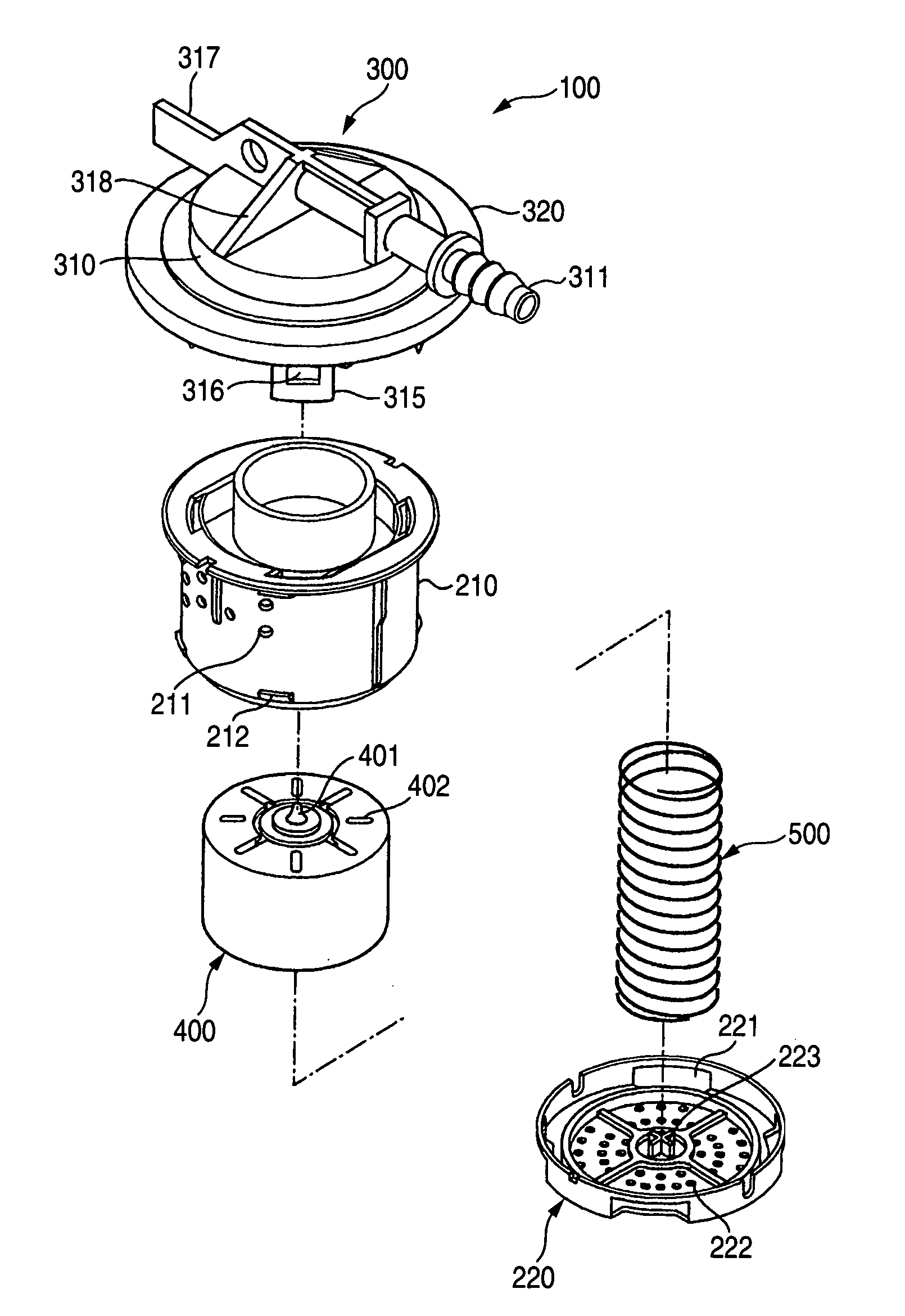
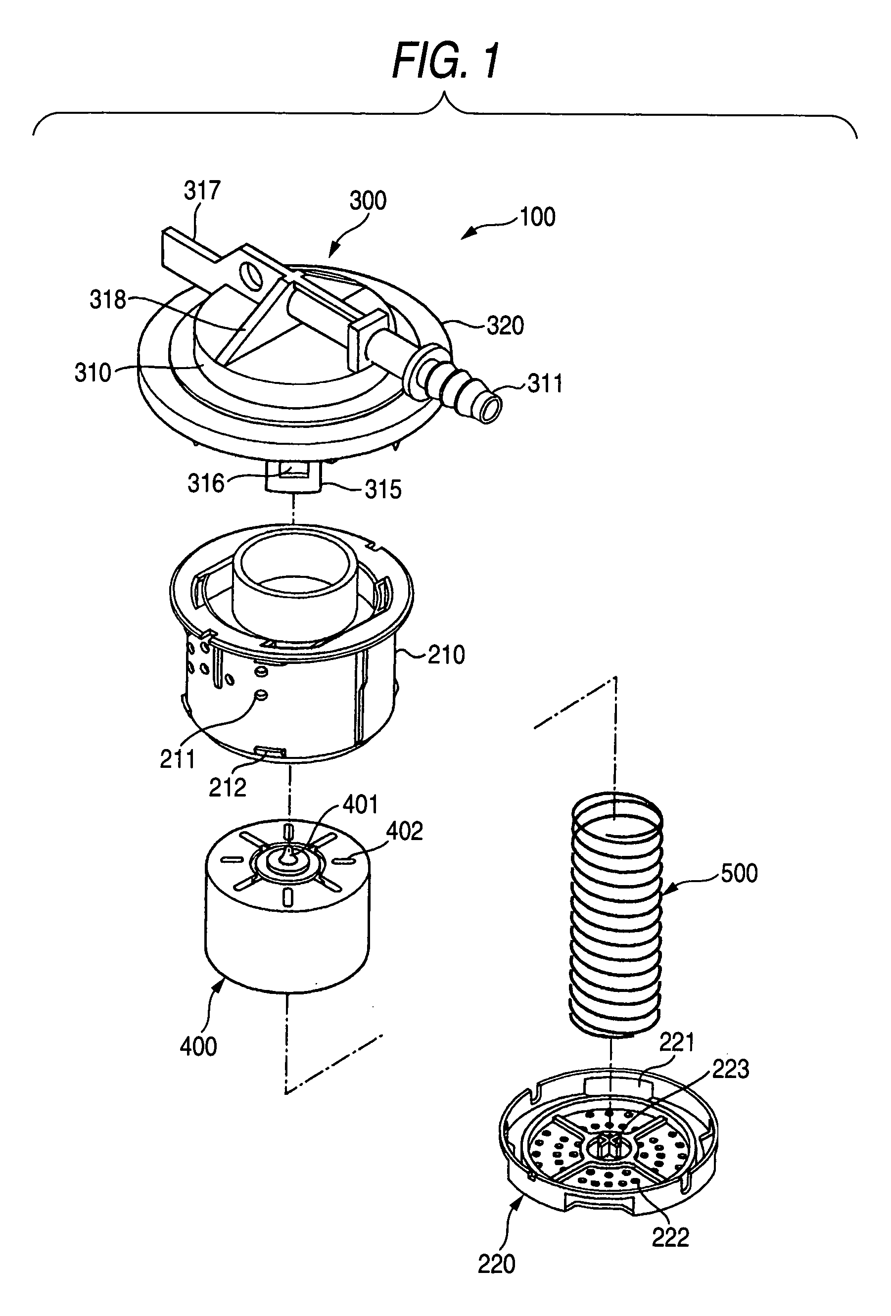
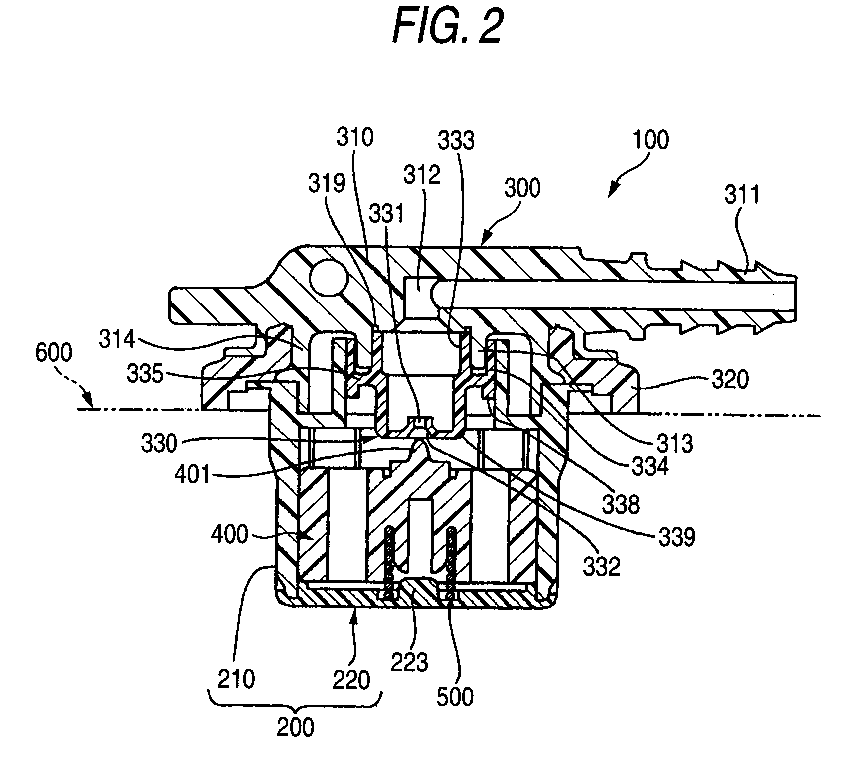
[0026] One embodiment of a float valve apparatus manufactured by the invention is shown in FIGS. 1 to 7. FIG. 1 is an exploded perspective view of a float valve apparatus, and FIG. 2 is a sectional view showing a state in which the float valve apparatus is mounted in a fuel tank, and FIGS. 3A and 3B are enlarged sectional views of a weld part in the case of spin welding a seal cap to a lid body and FIG. 3A is an enlarged sectional view before welding and FIG. 3B is an enlarged sectional view after welding, and FIG. 4 is a sectional view showing a state before spin welding in the case of spin welding the seal cap to the lid body, and FIG. 5 is a sectional view showing a state after spin welding in the case of spin welding the seal cap to the lid body, and FIG. 6 is a perspective view showing a welding method of the seal cap by a spin welding apparatus, and FIG. 7 is a perspective view showing a rotar...


PUM


Abstract

In a method for manufacturing a float valve apparatus including a valve case, an upper lid incorporated into this valve case to form a valve chamber, and a float valve liftably arranged inside the valve chamber, the upper lid being provided with a lead-out pipe connected to piping of the outside, an exhaust hole which communicates with this lead-out pipe and is opened in an inner surface of the upper lid, and a seal cap which is mounted so as to enclose this exhaust hole and forms a valve seat on which the float valve abuts, the seal cap is welded to an inner surface of the upper lid by spin welding.

Description

BACKGROUND OF THE INVENTION [0001] 1. Field of the Invention [0002] The present invention relates to a float valve apparatus suitable for a fuel shutoff valve etc. for preventing fuel from flowing out the outside of a fuel tank when a liquid level of the fuel tank of, for example, an automobile rises. [0003] 2. Description of the Related Art [0004] As a conventional float valve apparatus, a fuel outflow prevention valve of a vehicle characterized in that in a fuel outflow prevention valve of a vehicle including a tubular valve chamber in which an upper lid wall is had and the lower end is blocked by a filter and an exhaust hole of fuel vapor is upward opened in the center of the upper lid wall, a connection pipe integrally provided radially outward on the upper lid wall of the tubular valve chamber and in perpendicular communication with the upper end of the exhaust hole in the inner end, and a float which is vertically movably held in the tubular valve chamber and has a valve head ...

Claims


Application Information

Patent Timeline
IPC IPC(8): B60K15/01B29C65/00B29C65/06F16K24/04F16K27/00F16K31/18
CPCB29C65/0672B29C66/12441B29C66/322B29L2031/7506Y10T29/49416B29C65/069B29C66/5432B29C66/5344F16K24/044B29C66/53247B29C66/61B29C66/71B29C66/8322B29L2031/7172B29K2023/06B29K2059/00B29K2077/00
Inventor KISHI, MORIHIKO
Owner PIOLAX CO LTD
Why Eureka
Try Eureka