Variable nozzle control apparatus of turbocharger

Inactive Publication Date: 2005-02-03
MITSUBA CORP
View PDF9 Cites 17 Cited by
  • Summary
  • Abstract
  • Description
  • Claims
  • Application Information

AI Technical Summary

Benefits of technology

[0021] The invention has a first object to cause the system or apparatus to comprise an electronic control actuator, to control the electronic control actuator through a control signal line from an engine ECU, to control the opening of the vane of a variable nozzle provided in a turbocharger and to simply calculate the vane opening target position of the variable nozzle by the electronic control actuator to carry out an adaptation and a control to the actual opening position of the valve of the variable nozzle by controlling the position of the nozzle vane suitably in real tim

Problems solved by technology

Since the conventional art has the structure described above, there are the following problems.
Accordingly, there is a problem in that the duty solenoid valve 2 and the negative pressure actuator 3 are caused to generate a misarrangement in an operation by precision in the sensor, a temperature drift or the linear interpolation computing error of the data map and the opening of the variable nozzle cannot be controlled properly.
There is a problem in that the control software of the engine ECU 1 for carrying out a control operation to have an optimum value, and furthermore, for executing a deciding operation when the negative pressure actuato

Method used


Image

  • Variable nozzle control apparatus of turbocharger
  • Variable nozzle control apparatus of turbocharger
  • Variable nozzle control apparatus of turbocharger

Examples


first embodiment

[0047] First Embodiment

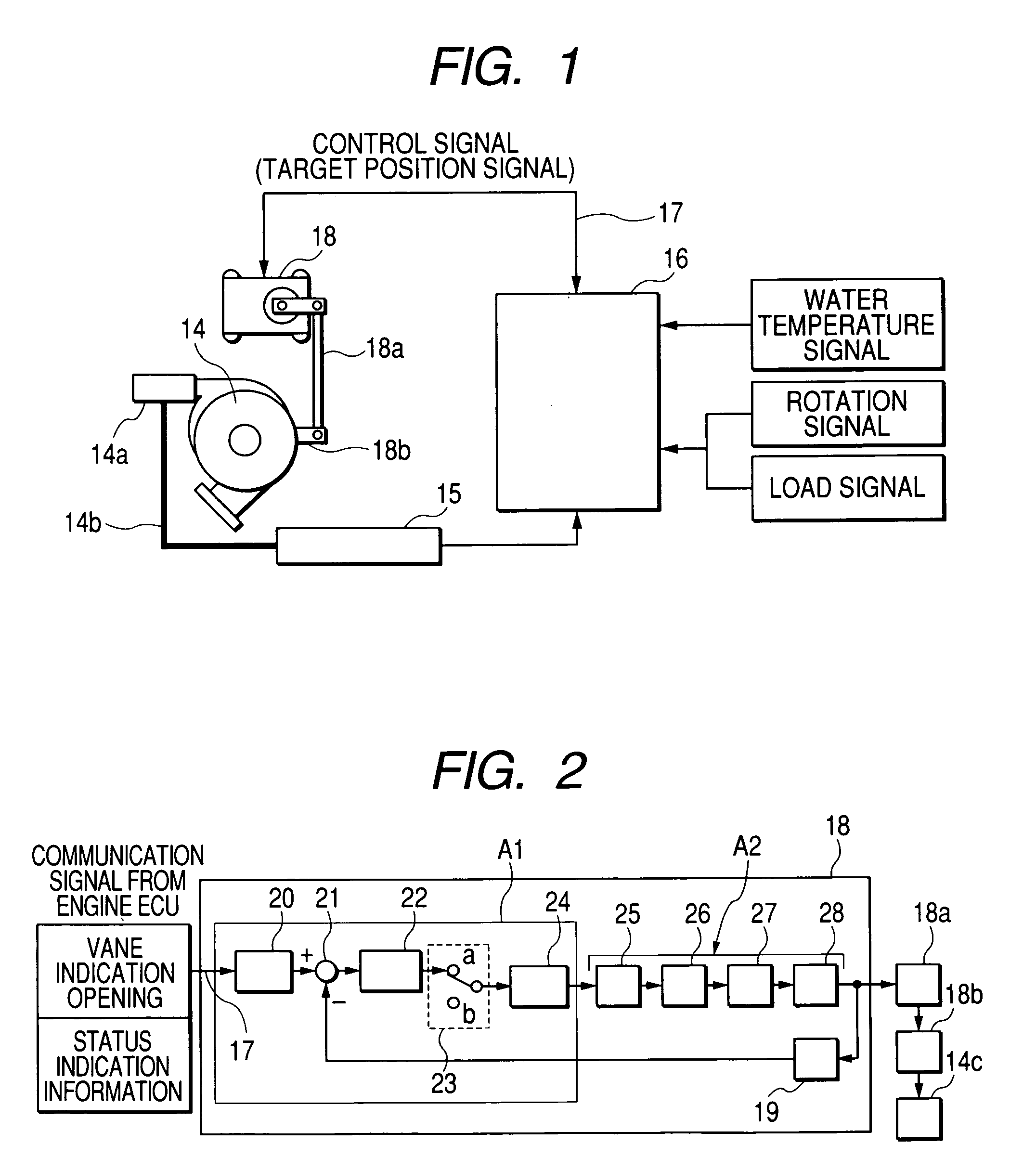
[0048] Next, the first embodiment of the variable nozzle control apparatus of the turbocharger according to the invention and an operation thereof will be described with reference to FIGS. 2 and 3.

[0049]FIG. 2 is a block diagram showing the variable nozzle control apparatus of the turbocharger according to the first embodiment of the invention. Description will be given to the first embodiment.

[0050] The electronic control actuator 18 comprises an electronic control circuit section A1 and a driving section A2. The actual angle signal of an output shaft is fed back from the output side of the driving section A2 to the comparing device of the electronic control circuit section A1 through an angle sensor 19. In the electronic control circuit section A1, an angle signal converting device 20, a comparing device 21, a calculating device 22 constituted by a PID calculating section, a change-over switch 23 and a motor driving logic generating device 24 are sequentia...

second embodiment

[0055] Second Embodiment

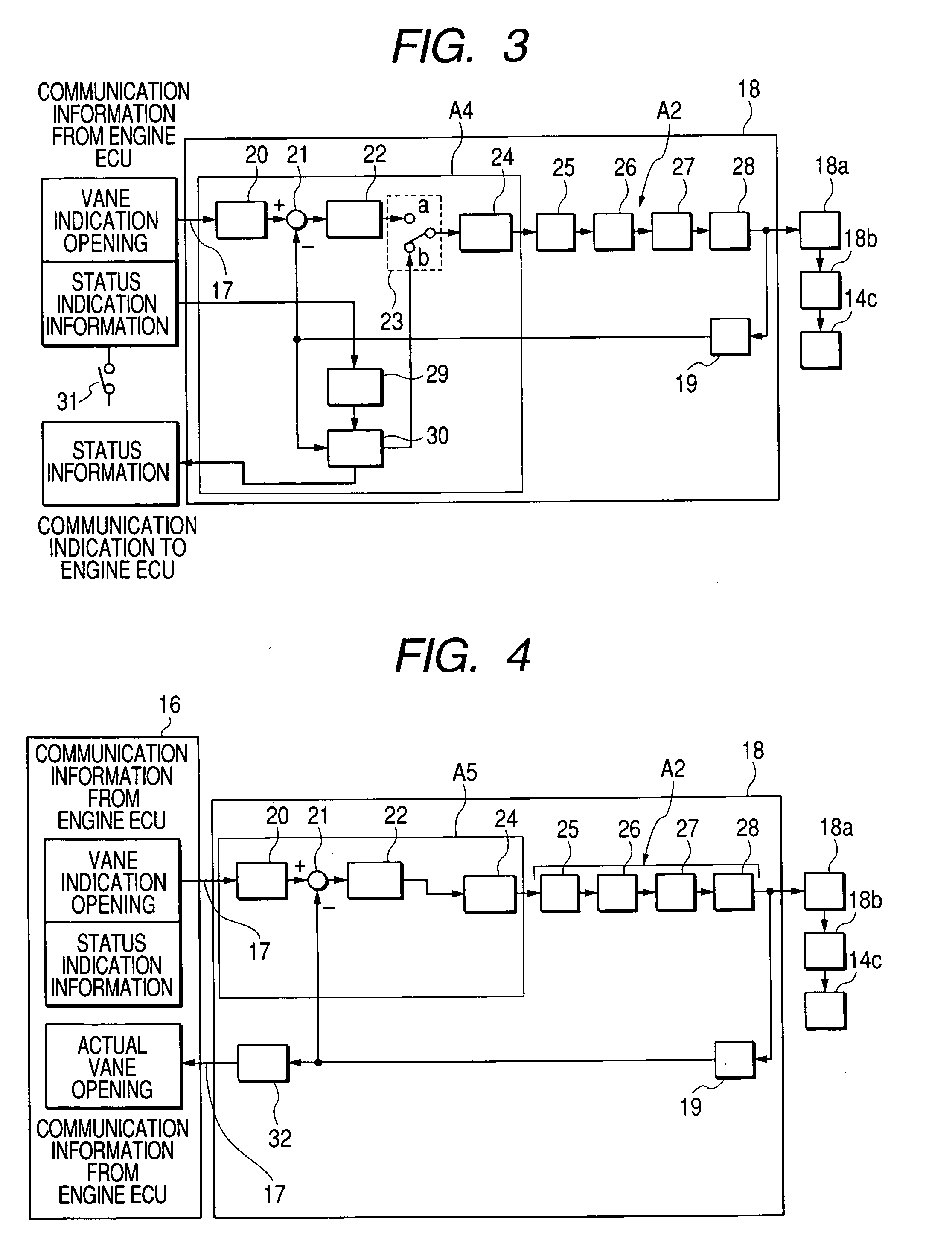
[0056]FIG. 3 is a block diagram showing the variable nozzle control apparatus of the turbocharger according to the second embodiment of the invention. Description will be given to the second embodiment. FIG. 3 is a diagram showing a structure in which a function of causing the vane 14c of the variable nozzle to carry out a wiping operation is added to the structure of the block circuit in FIG. 2.

[0057] The electronic control actuator 18 comprises an electronic control circuit section A4 and the driving section A2. The driving section A2 and the other structures are the same as those in the first embodiment and description thereof will be omitted. Moreover, the structure of the electronic control circuit section A4 is the same as that of the electronic control circuit section A1 except that wiping command device and wiping processing device which will be described below are added. The electronic control circuit section A4 includes a wiping command device 29 a...

third embodiment

[0061] Third Embodiment

[0062]FIG. 4 shows is a block diagram showing the third embodiment of the variable nozzle control apparatus of the turbocharger according to the invention. Description will be given to the third embodiment.

[0063] The electronic control actuator 18 includes an electronic control circuit section A6 and a driving section A2 that is controlled and driven by the electronic control circuit section A5. The electronic control circuit section AS includes an angle signal converting device 20 for introducing an indication signal for the opening of the vane of the variable nozzle through a control signal line 17, a comparing device 21 for comparing a target angle signal of the output shaft with an actual angle signal of the output shaft, a calculating device 22 constituted by a PID calculating section for carrying out integration, differentiation and proportional control to the output signal from the comparing device 21, a motor driving logic generating device 24 connect...


PUM


Abstract

The invention provides a variable nozzle control apparatus for a turbocharger in an engine comprising: a variable nozzle having a vane; an engine ECU for identifying an operating situation of the engine by detected outputs of sensors in the engine and outputting a control signal; and an electronic control actuator for controlling an opening of the vane in response to the control signal transmitted from the engine ECU, wherein the electronic control actuator includes an electronic control circuit section for receiving an opening indication information of the vane from the engine ECU and outputting an output signal; a driving section for receiving the output signal from the electronic control circuit and driving the vane of the variable nozzle through an output shaft; and an angle sensor for detecting a rotation angle of the output shaft to output an actual angle signal of the output shaft to the electronic control circuit.

Description

[0001] The present application is a CIP application of U.S. patent application Ser. No. 10 / 776,348, filed on Feb. 12, 2004, the entire contents of which are incorporated herein by reference. [0002] The present application is based on Japanese Patent Applications No. 2003-34633 and No. 2003-182500, the entire contents of which are incorporated herein by reference.BACKGROUND OF THE INVENTION [0003] 1. Field of the Invention [0004] The present invention relates to a variable nozzle control apparatus of a turbocharger for controlling the opening of the vane of a variable nozzle of a turbocharger mounted on a car by means of an electronic control actuator in response to a control signal transmitted from an engine ECU. [0005] 2. Related Art [0006] Conventionally, a technique for controlling the opening of the vane of a variable nozzle of a turbocharger mounted on a car of this type has a structure shown in FIG. 8, for example. [0007] Description will be given to the structure. 1 denotes a...

Claims


Application Information

Patent Timeline
IPC IPC(8): F02B37/24F02D41/00F02D41/10
CPCF02B37/12F02B37/24Y02T10/144F02D41/0007F02D41/10F02B39/00Y02T10/12
Inventor ANDO, YOSHIYUKISAITO, HARUOSEKINE, TAKAAKI
Owner MITSUBA CORP
Why Eureka
Try Eureka