
Well chemical treatment utilizing plunger lift delivery system

a technology of chemical treatment and pumping system, which is applied in the direction of fluid removal, sealing/packing, borehole/well accessories, etc., can solve the problems of reducing the production rate, affecting and insufficient gas flow to carry liquid out of the well, so as to increase the efficiency of chemical treatment. the effect of the delivery

Inactive Publication Date: 2005-02-03
CONOCOPHILLIPS CO
View PDF22 Cites 18 Cited by
  • Summary
  • Abstract
  • Description
  • Claims
  • Application Information

AI Technical Summary

Benefits of technology

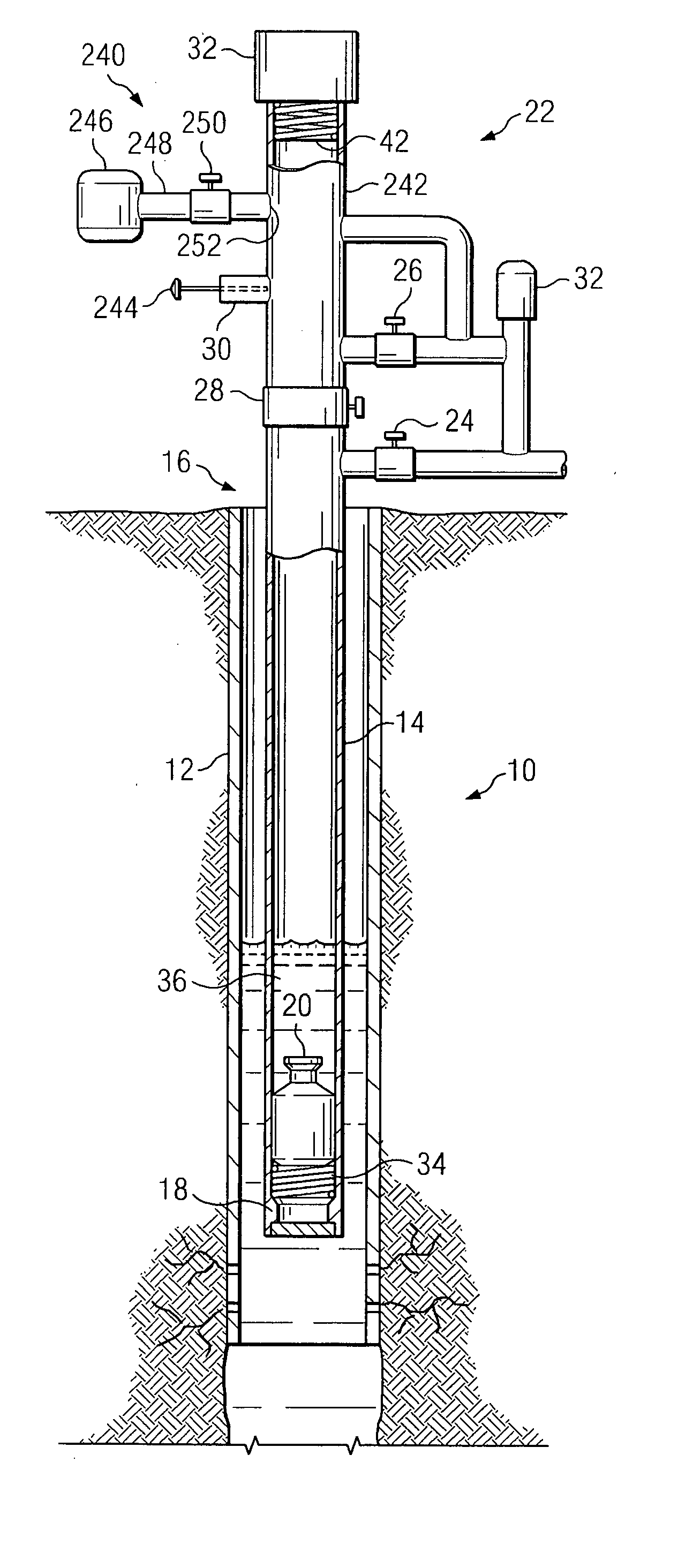
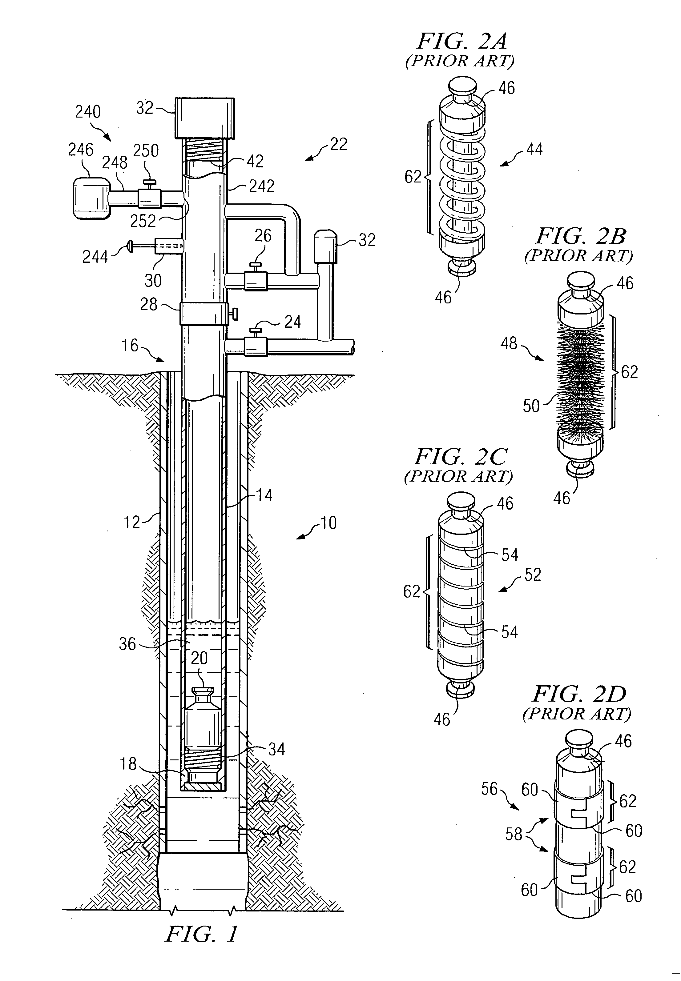
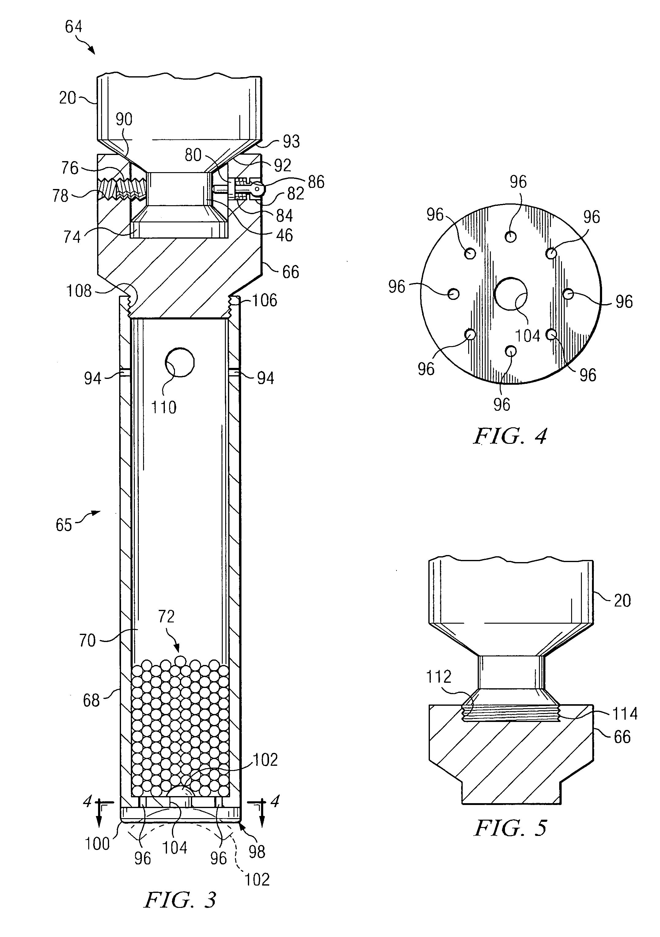
[0027] Also, in a preferred embodiment of the invention, the dispenser may include an extension or standoff section which allows the receptacle holding the treatment chemical to be positioned below the lower end of the tubing when the plunger assembly comes to rest at the bottom of the well. This allows the treatment chemical to be dissolved into or mixes with the liquid located in the near wellbore area, thereby increasing the efficiency of the chemical delivery.

Problems solved by technology

At some point in time the flow rate of gas will be insufficient to carry liquids out of the well, e.g., carry water and petroleum condensates, to the surface.
This liquid will exert back pressure on the formation which will further decrease the production rate from the formation, and in some cases cause production to cease altogether.
As a result, the bottom of the well is subject to corrosion, scale, paraffin deposits, deposits of petroleum distillates and other undesirable deposits.
These techniques have many drawbacks, especially when they are employed with plunger lift production methods.
This continuous treatment approach usually requires a conduit to deliver the chemical to the bottom of the well and uses an unnecessarily large amount of chemicals.
The method is not reliable, and is unsuitable for use in some wells due to lack of perforations to retain the residual chemical, or because well production rates are so high as to quickly remove the chemicals.

Method used


Image

  • Well chemical treatment utilizing plunger lift delivery system
  • Well chemical treatment utilizing plunger lift delivery system
  • Well chemical treatment utilizing plunger lift delivery system

Examples


Embodiment Construction

[0032] For purposes of background, an abbreviated discussion of the plunger lift technique will be presented. Those skilled in the art will recognize that there are many variations which have been used to the lift technique and system which is described. The preferred embodiment of the invention specifically described can be modified for variations of the described lift system. Further, those skilled in the art will appreciate that the present invention need not be used to the exclusion of other chemical treatment methods. Costs and other considerations can result in the use of the present invention together with other treatment methods.

[0033] The petroleum well will have a wellbore 10 which typically contains a casing 12 either throughout the entire bore or a portion of the wellbore. The wellbore 10 can also contain tubing 14 within the casing 12. In a typical arrangement, the well production will flow through the tubing 14 to the wellhead 16. For purposes of illustrating the inve...


PUM


Abstract

An apparatus and method for delivery of treatment chemicals to the bottom of the wellbore. The delivery system can be a chemical dispenser which can be attached to a plunger used in plunger lift operations, a plunger which has been impregnated with treatment chemicals, a plunger / dispenser apparatus which has an interface section for interfacing with the inside of the tubing and a dispenser section. Automatic recharging or reapplication of chemicals to the chemical delivery system can be accomplished with a chemical application assembly attached to the plunger manifold.

Description

TECHNICAL FIELD [0001] The present invention relates to petroleum production and has significant application to gas wells which use plunger lift systems to aid in production from the well. In particular, the invention relates to delivery of treatment chemicals downhole to prevent to scale deposits, paraffin buildup, and corrosion and for other purposes. BACKGROUND OF THE INVENTION [0002] This invention relates to production from petroleum wells, and in particular, the delivery of chemicals downhole. The invention will find the greatest use in wells which produce gas. Thus, the background description and the description of the preferred embodiments of the invention will focus on gas wells. [0003] Typically, as gas is produced from a well the production decreases as the pressure in the formation decreases with the quantity of gas produced from the well. Usually, a well produces not only gas but also liquids, such as water and petroleum condensates with some asphaltines. As the pressur...

Claims


Application Information

Patent Timeline
IPC IPC(8): E21B27/02E21B33/068E21B37/06E21B43/12E21B43/25
CPCE21B27/02E21B33/068E21B43/25E21B43/121E21B37/06
Inventor WILSON, DENNIS RAY
Owner CONOCOPHILLIPS CO
Learn More