Porous getter devices with reduced particle loss and method for manufacturing same

a technology of porous getter and particle loss, which is applied in the direction of machines/engines, plasma technology, metallic material coating process, etc., can solve the problems of reducing the porosity and the exposed area of active materials, the possibility of particle loss, and the pain of free particles, so as to improve the cleaning of the working atmosphere and reduce the evacuation time

Inactive Publication Date: 2005-02-03
SAES GETTERS SPA
View PDF12 Cites 4 Cited by
  • Summary
  • Abstract
  • Description
  • Claims
  • Application Information

AI Technical Summary

Benefits of technology

[0014] The present invention uses the discovery that the deposition of a suitable material in low thickness on the surface of a porous getter body does not prejudice the gas sorption properties, and sensibly reduces the phenomenon of particle loss at the same time. This discovery is in contrast to what was originally thought by many of those skilled in the art regarding deposition materials on a porous getter body.
[0015] The present invention is also particularly useful for the manufacture of a particular type of getter device, having the shape and size of a substrate to be treated in a deposition chamber such as in a process chamber of the microelectronic industry, wherein the getter device guarantees a lower evacuation time and a better cleaning of the working atmosphere: this kind of getter device is described in international patent application PCT / IT00 / 00136 in the name of the applicant.

Problems solved by technology

A problem encountered with the getter devices according to the above-described known art is the possibility of the loss of particles due to the fact that the surface particles of the getter tend to be bound more weakly than the internal particles.
The presence of free particles is painful for most of the anticipated applications of the getter devices, because such free particles may interfere with the functionality of the device.
However, this method not only reduces the entity of the particle loss problem without solving it, but also has the disadvantage that it leads to a reduction of the porosity and of the exposed area of the active material, which results in a reduction of the gas sorption properties of the getter devices.

Method used


Image

  • Porous getter devices with reduced particle loss and method for manufacturing same
  • Porous getter devices with reduced particle loss and method for manufacturing same
  • Porous getter devices with reduced particle loss and method for manufacturing same

Examples


Embodiment Construction

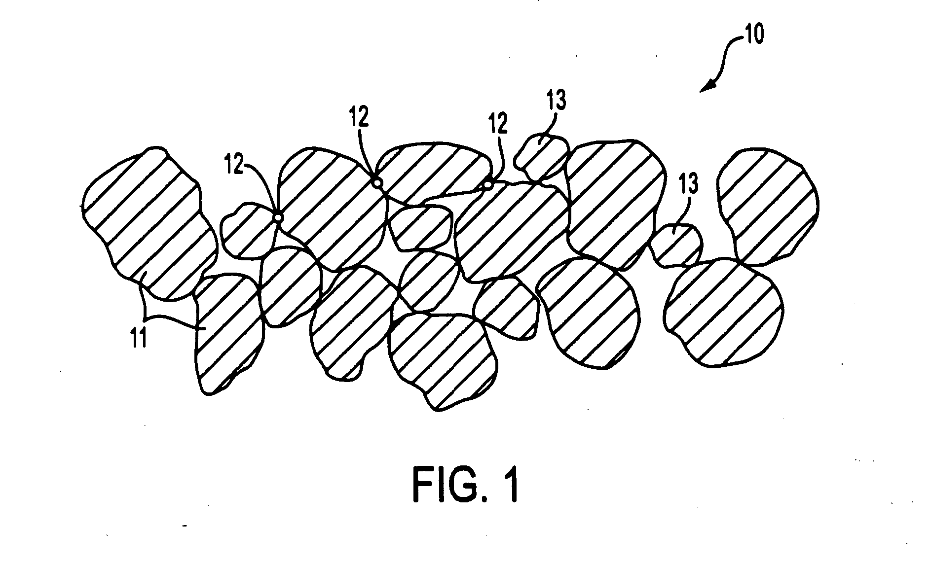
[0020] Referring now to FIG. 1, a cross-section of the surface portion of a porous getter body 10 is shown. The particles of getter material 11 are connected together through “necks”12, wherein during the sintering process, microfusions of the material 11 take place. The adhesion of the surface particles to the rest of the structure can be reduced because of a scarce mechanical resistance of these necks (due to a low temperature of the sintering process) or to their reduced number, in particular in the case of particles 13 of a small size.

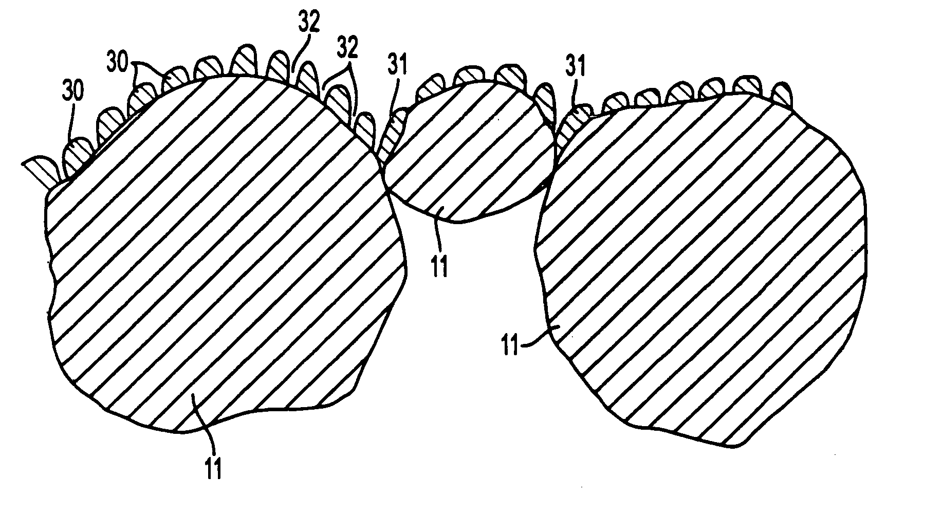
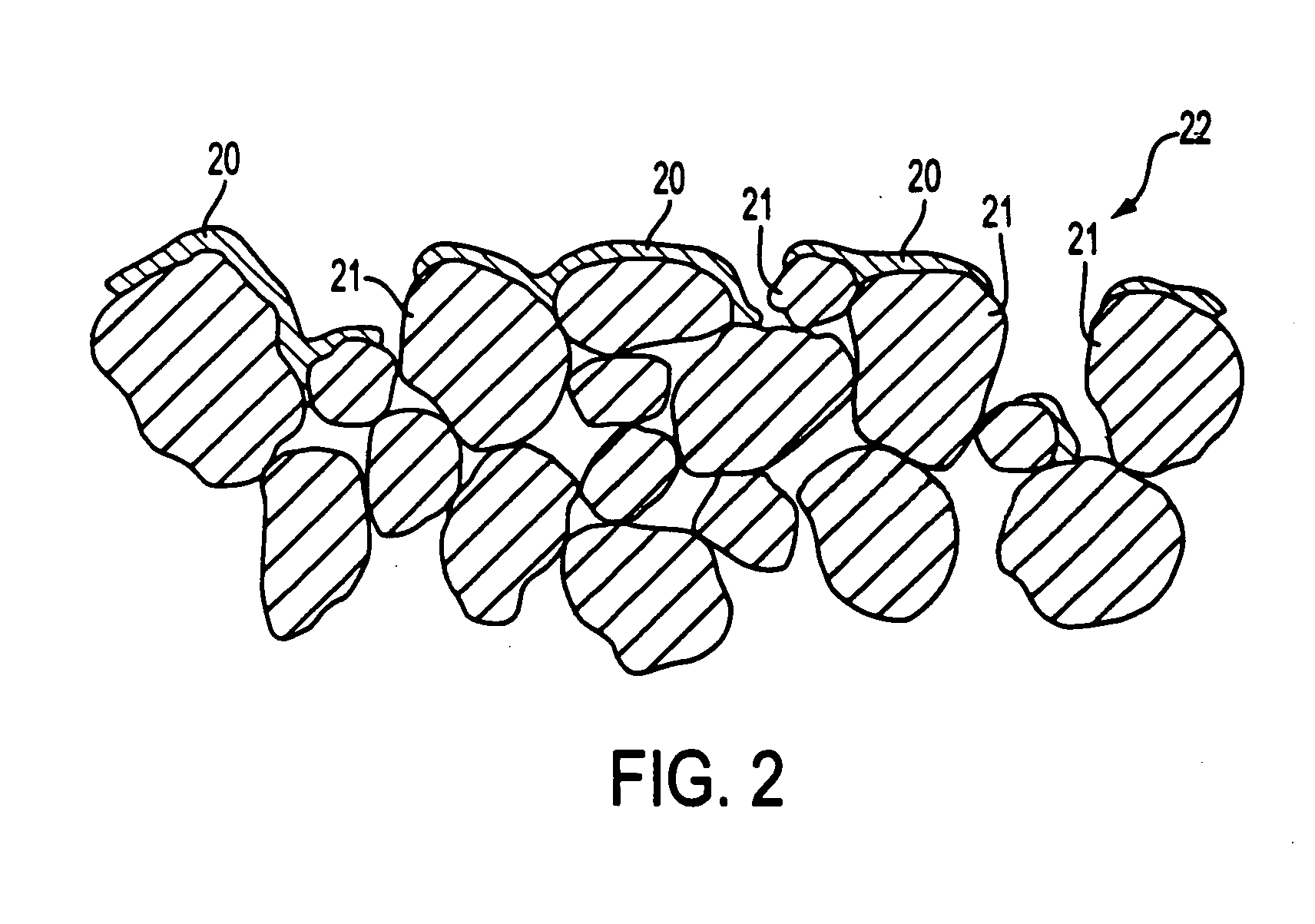
[0021]FIG. 2 represents the same body of FIG. 1 with a covering according to the method of the present invention. The upper surface of body 10 is covered with a layer 20 obtained by one of the cited techniques, which will be detailed below. These techniques are directional, and as such, the deposit 20 covers only the portion of body 10 which is exposed towards the source of the material which is to be deposited. Some zones 21 of the surface getter...


PUM

PropertyMeasurementUnit
thickaaaaaaaaaa
temperaturesaaaaaaaaaa

Abstract

A method for reducing the loss of particles from the surface of porous getter bodies is taught herein. The method consists in producing on the surface of the porous getter a thin layer of a metal or metal alloy with a deposition technique selected among the deposition of materials from arc generated plasma, ionic beam deposition and cathodic deposition. The deposition technique allows for granular or columnar surface of the covering material but still allowing access to the surface of the getter material, resulting in a reduced getter particle loss.

Description

CROSS REFERENCE TO RELATED APPLICATIONS [0001] This application claims priority under 35 U.S.C. 119 to Italian patent application MI-2000-A-002099 filed Sep. 27, 2000, which is incorporated by reference herein for all purposes. FIELD OF THE INVENTION [0002] The present invention relates to a reduced particle loss porous getter devices and the method for manufacturing such reduced particle loss getter devices. BACKGROUND OF THE INVENTION [0003] Getter devices can be used in all the technological and scientific applications wherein vacuum maintenance is required, such as, for example, flat displays (of the plasma or field emission type), some kind of lamps or particle accelerators for scientific research. Another important field of use of the getter devices is gas purification, inside fluorescent lamps but mainly in the case of the process gases for microelectronic industry. [0004] The active materials which form these getter devices are mainly zirconium and titanium and alloys thereo...

Claims


Application Information

Patent Timeline
Patent Type & Authority Applications(United States)
IPC IPC(8): B01J20/02B22F3/11C22C1/04C22C14/00C22C16/00C23C4/08C23C4/12C23C14/14C23C14/16C23C14/24C23C14/34C23C14/46F04B37/04H01J7/18
CPCB22F3/1146B22F2998/00C22C1/0458C23C14/16Y10T428/24298H01J7/183Y10T428/12021Y10T428/12479B22F1/0003B22F1/09
Inventor CONTE, ANDREAMORAJA, MARCO
Owner SAES GETTERS SPA
Why Eureka
Try Eureka