Autoclave molding system for carbon composite materials

Inactive Publication Date: 2005-02-03
SAMPSON JAMES K
View PDF5 Cites 34 Cited by
  • Summary
  • Abstract
  • Description
  • Claims
  • Application Information

AI Technical Summary

Benefits of technology

[0020] It is an object of at least one embodiment of the present invention to provide a thermal molding method (such as autoclave molding) for molding a part having a relatively low coefficient of thermal expansion, wherein the method involves a mold that is simple and easy to make relative to conventional methods.
[0021] It is an object of at least one embodiment of the present invention to provide a thermal molding method (such as autoclave molding) for molding a part having a certain coefficient of thermal expansion, wherein the method involves a mold made from a material whose coefficient of thermal expansion sufficiently matches that coefficient of thermal expansion of the part to be molded, and avoiding difficulties attendant convention methods involving sufficiently matching of coefficients of thermal expansion; and / or abate the risk that rapid depressurization of the mold and part results in separation (e.g., explosive separation) of the part molding element from the mold.
[0022] It is an object of at least one embodiment of the present invention to provide a method by which a mold having a relatively low coefficient of thermal expansion may be created, wherein the method enhances the elimination of vacuoles such as gas bubbles that otherwise might negatively affect the shape of the molding surface, or that would otherwise require additional treatment of the molding surface.

Problems solved by technology

Of relevant note is the tendency of pieces of unidirectional or multi-direction fiber fabric, or pieces of tow, to line up in certain identifiable directions when their length exceeds a certain limit, thus compromising the achievement of isotropy.

Method used


Image

  • Autoclave molding system for carbon composite materials
  • Autoclave molding system for carbon composite materials
  • Autoclave molding system for carbon composite materials

Examples


Embodiment Construction

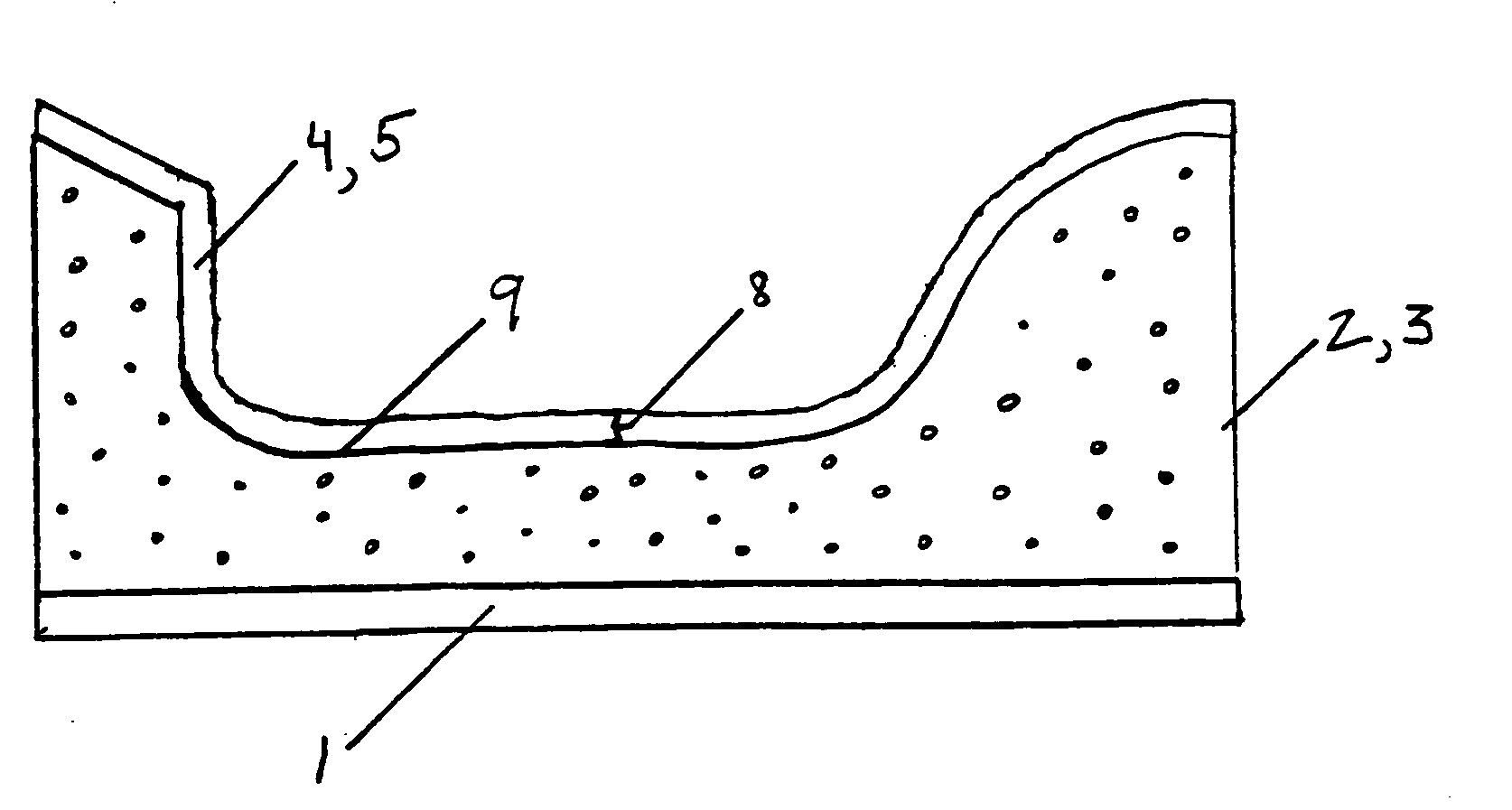
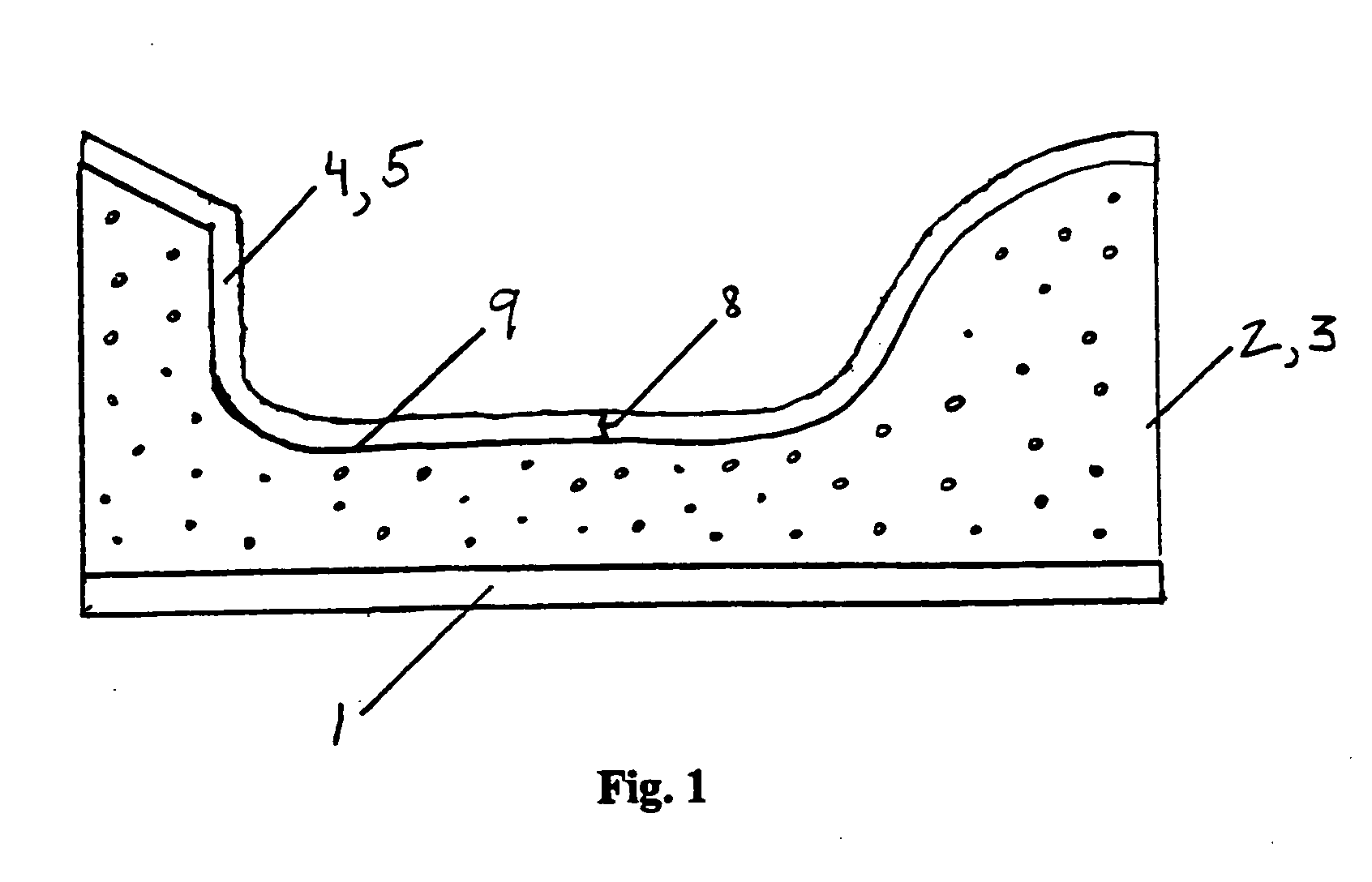
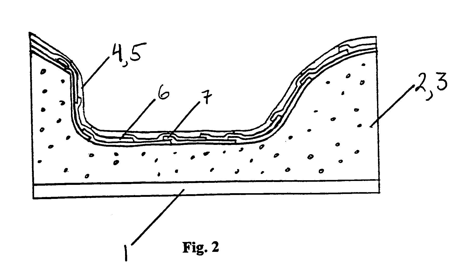
[0053] As mentioned earlier, the present invention includes a variety of aspects that may be combined in different ways. Several of these aspects are first discussed separately. Contemplated by at least one embodiment of the instant invention is a novel process of thermally molding (e.g., autoclave molding) a part. One reason this new manner of molding may be particularly valuable is its elimination of any the loss of dimension, spatial or shape accuracy of the mold that is attributable to the aforementioned copying inherent in conventional methods. Further, and at least with respect to molding a part having a relatively low coefficient of thermal expansion, this new method may be valuable because it enables sufficient matching of the coefficients of thermal expansion of the mold and the part without the disadvantages of the three conventional methods presented above. At least one embodiment of this method may essentially involve establishing (by rough machining, machining out, sand...


PUM

PropertyMeasurementUnit
Fractionaaaaaaaaaa
Fractionaaaaaaaaaa
Fractionaaaaaaaaaa

Abstract

In one basic form, at least one embodiment of the invention discloses an autoclave molding process to mold a part having a certain coefficient of thermal expansion, wherein the mold involves a sufficiently gas permeable material that serves as a mold foundation and that has a coefficient of thermal expansion that sufficiently matches that of the part to be molded (which may be relatively low), in combination with a two or three dimensionally isotropic, part molding element that also has a sufficiently matching coefficient of thermal expansion and that is made from short reinforcement fiber material, with the intended result that risk of unacceptable deformation such as breaking of the material to be molded is sufficiently abated.

Description

[0001] This application claims the benefit of U.S. provisional application Ser. No. 60 / 466,786 filed on Apr. 29, 2003, and of U.S. provisional application Ser. No. 60 / 542,673 filed Feb. 6, 2004, each incorporated herein by reference.BACKGROUND OF THE INVENTION [0002] The desire to create load-bearing structures that are lighter and stronger than materials such as steel, aluminum, metals in general, and fiberglass, has been know in some industries for some time. Materials such as composite structures may comprise fibers (whether woven, straight, randomized, long, or filamentary, or in any other shape or configuration) for fiber reinforcement, in addition to a matrix. The matrix can be, but is not limited to, polymeric resin or carbon resin (such as amorphous carbon resin), and may serve to provide adhesion among the fibers. Such fiber reinforcement composite structures (or fiber composites) are different from powder or particle composite structures which, instead of providing enhance...

Claims


Application Information

Patent Timeline
IPC IPC(8): B29BB29C33/10B29C33/56B29C43/00B29C43/02B29C70/44
CPCB29C33/10B29C33/565B29C43/003B29K2995/0012B29K2105/04B29K2105/06B29C70/44
Inventor SAMPSON, JAMES K.
Owner SAMPSON JAMES K
Why Eureka
Try Eureka