Method for upgrading an optical transmission system and an optical transmitter

a technology of optical transmission system and optical transmitter, which is applied in the direction of transmission monitoring, multiplex communication, wavelength-division multiplex system, etc., can solve the problems of deterioration of signal lights of respective signal wavelengths, inability to achieve desired transmission characteristics, and practicably impossible to reproduce the gain profile in full implementation, so as to achieve satisfactory transmission characteristics, reduce nonlinear penalties of signal wavelengths, and facilitate actual operation

Inactive Publication Date: 2005-02-03
KDDI SUBMARINE CABLE SYST +1
View PDF9 Cites 47 Cited by
  • Summary
  • Abstract
  • Description
  • Claims
  • Application Information

AI Technical Summary

Benefits of technology

[0008] One embodiment of the invention is a method for upgrading a wavelength division multiplexing optical transmission system. First, a transmission wavelength band in an optical transmission line designed for wavelength-division-multiplexing is divided into a plurality of sub-bands. Signal lights or an amplified spontaneous emission (“ASE”) dummy light is disposed per sub-band to function as a transmission unit. By increasing the optical power of new signal lights in a first sub-band to which no ASE dummy light is disposed, the new signal lights are added. While the new signal lights are being added, the optical power of the ASE dummy light in the first sub-band is controlled so that the transmission characteristics such as the gain profile or receiving SNR of the existing signal lights can be maintained approximately to a fixed level.
[0009] Preferably, second new signal lights are added in a second sub-band to which an ASE dummy light is disposed by increasing the optical power of the second new signal lights in the second sub-band while decreasing the optical power of the ASE dummy light in the second sub-band. While the second new signal lights are being added, the optical power of the other ASE dummy lights is controlled so that the transmission characteristics of the existing signal lights and new signal lights can be maintained approximately to a fixed level.
[0013] That is, when the signal wavelengths are added, the insertion of signal lights and the power control of the ASE dummy light in the adjacent sub-bands are performed per sub-band. This operation hardly affects the existing signal channels and accordingly it is possible to control the fluctuations of the optical power and receiving SNR of the existing signal channels. Consequently, the new signal wavelengths can be added in-service and furthermore the actual operation becomes easier.
[0014] Since the ASE dummy light is used, it is possible to obtain the gain profile close to the one expected in the design stage of the optical transmission line, namely the one obtained in the full-implementation, with fewer light sources. By assigning ASE dummy lights instead of signal wavelengths that are not used yet, nonlinear penalties of signal wavelengths can be reduced. Because of those merits, even though fewer signal wavelengths are used compared to the designed number of signal wavelengths, it is likely to realize satisfactory transmission characteristics as planned in the design specification.

Problems solved by technology

When only discrete signal wavelengths are input into an optical transmission line designed for obtaining optimum input / output characteristics at full implementation, signal lights of respective signal wavelengths deteriorate due to nonlinear effects in the optical transmission line.
The desired transmission characteristics, therefore, cannot be realized.
As described in the above references, in such a configuration that one CW dummy laser light having a narrow spectral line-width substitutes a plurality of signal wavelengths, it is practically impossible to reproduce the gain profile in the full implementation.
As a result, when new signal wavelengths are added, the gain profile in an optical transmission line greatly fluctuates and the channel power and receiving signal to noise ratio (SNR) of existing signal wavelengths severely fluctuate.
The signal transmission becomes unstable immediately after the addition of the signal wavelengths, and close adjustments in the signal transmission are required.

Method used


Image

  • Method for upgrading an optical transmission system and an optical transmitter
  • Method for upgrading an optical transmission system and an optical transmitter
  • Method for upgrading an optical transmission system and an optical transmitter

Examples


Embodiment Construction

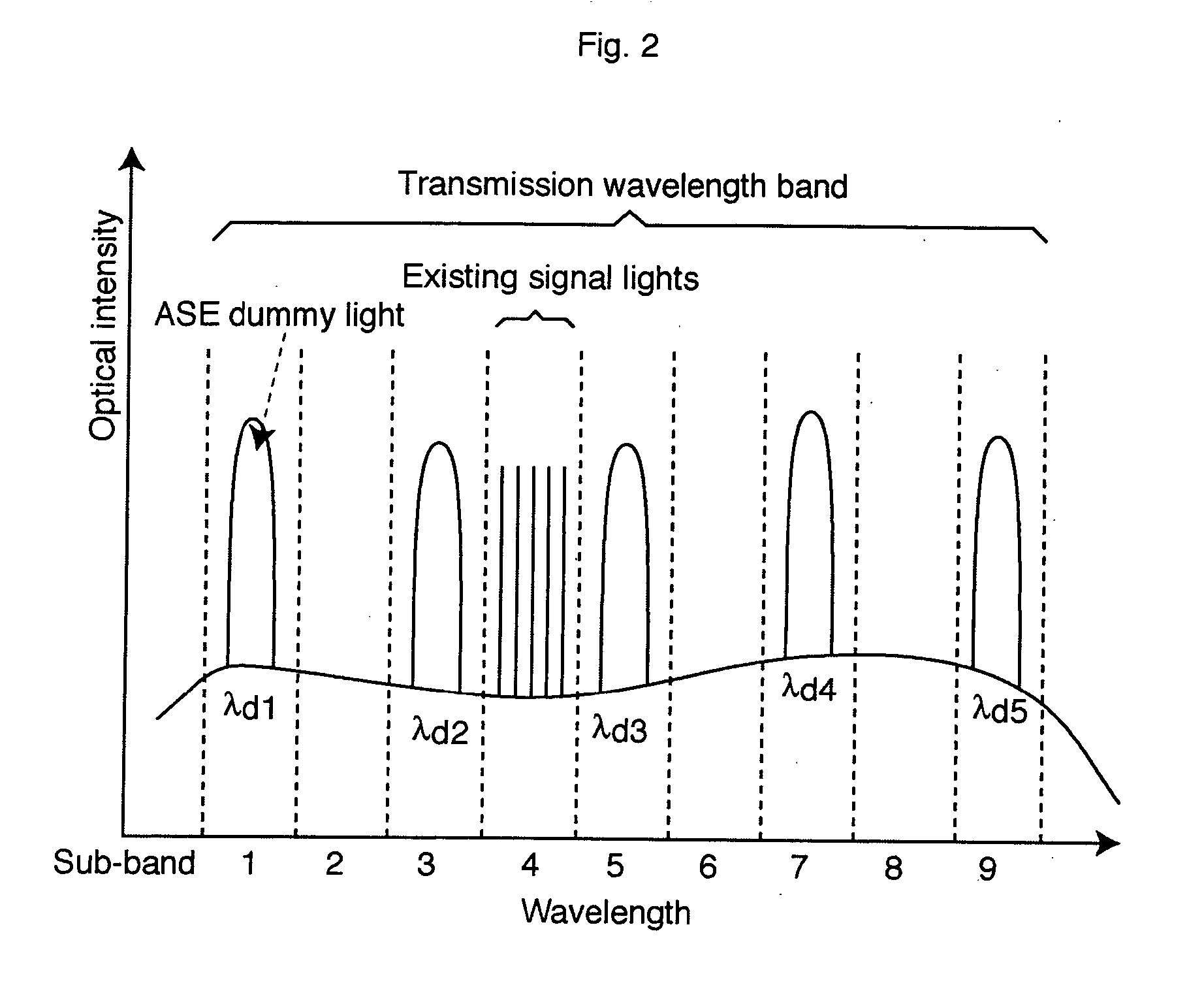
[0023] Exemplary embodiments of the invention are explained below in detail with reference to the drawings. In one embodiment, a transmission wavelength band in an optical transmission line at a full-implementing state, i.e. a transmission wavelength band in the design specification, is divided into a plurality of sub-bands having a specific wavelength width and signal lights or ASE dummy light are disposed per sub-band.

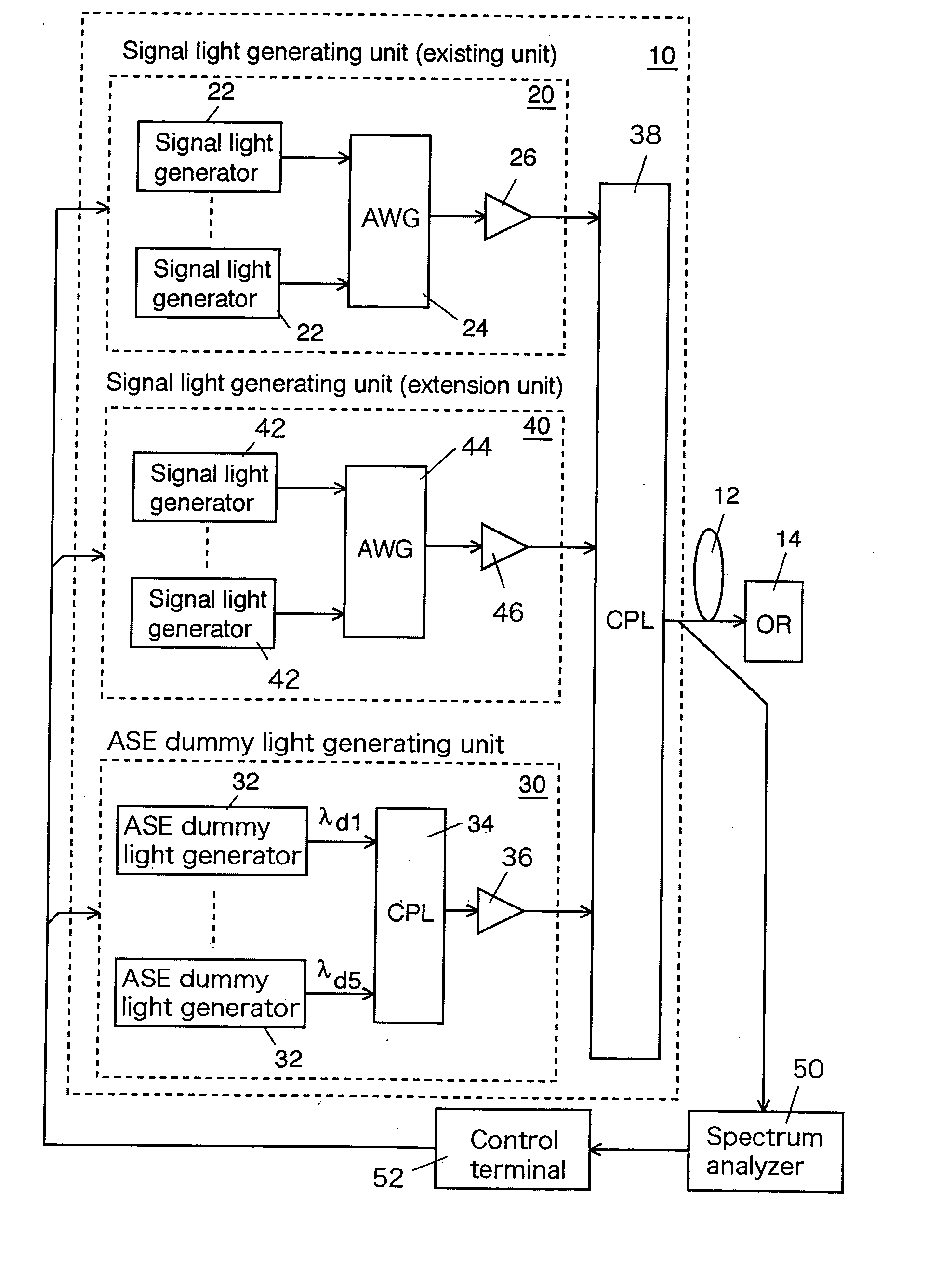
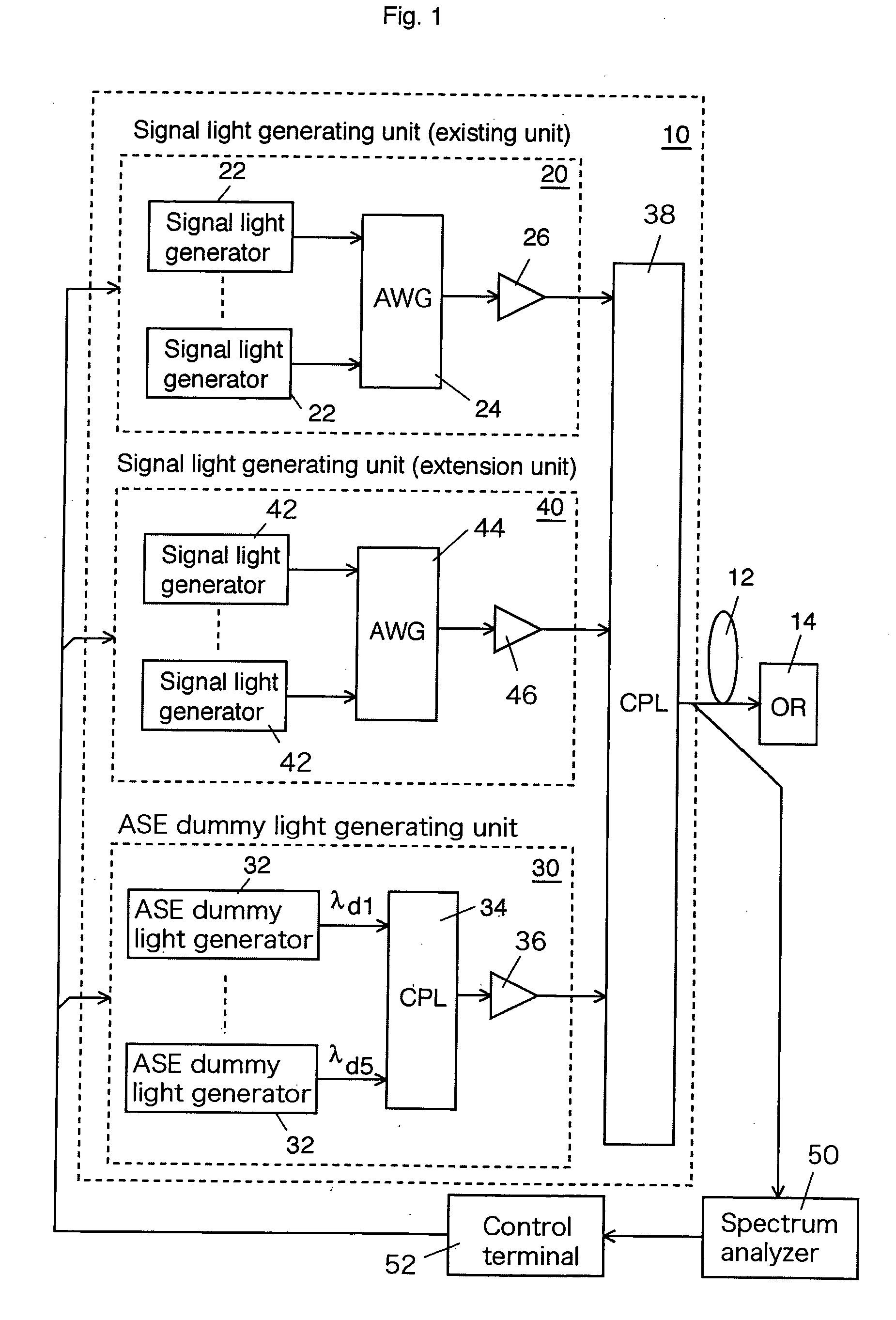
[0024]FIG. 1 shows a schematic block diagram of a WDM transmission system upgraded by an exemplary embodiment according to the invention, FIG. 2 shows an example of a wavelength map before the upgrading, FIG. 3 shows an example of a wavelength map during the upgrading, and FIG. 4 shows an example of a wavelength map after the upgrading. In FIGS. 2, 3, and 4, the horizontal axis expresses sub-bands and the vertical axis expresses optical intensity.

[0025] An optical transmitter 10 outputs a plurality of signal lights and a plurality of ASE dummy lights, each having a...


PUM


Abstract

A transmission wavelength band in an optical transmission line is divided into a plurality of sub-bands and signal lights or an ASE dummy light is disposed per sub-band as a unit. The optical power of the ASE dummy light in each sub-band is controlled so as to realize the gain profile at a full implementation in the optical transmission line. While new signal lights are being added, the optical power of whole ASE dummy lights or the optical power of the ASE dummy lights in sub-bands adjacent to the sub-band in which the new signal lights are to be added is controlled while increasing the optical power of the new signal lights so that the transmission characteristics of the existing signal lights are not affected by the signal addition.

Description

CROSS REFERENCE TO RELATED APPLICATIONS [0001] This application claims priority to Japanese Patent Application No. 2003-282807, filed Jul. 30, 2003, the entire contents of which are incorporated herein by reference. FIELD OF THE INVENTION [0002] This invention generally relates to a method for upgrading an optical transmission system and an optical transmitter, and more specifically relates to a method for upgrading a wavelength division multiplexing (WDM) optical transmission system and an optical transmitter for the method. BACKGROUND OF THE INVENTION [0003] In a typical WDM optical communication system, the optical transmission spectrum is divided into a few discrete signal wavelengths in order to save initial implementing costs. However, optical repeaters are typically implemented in an optical transmission line according to a specification designed for full implementation. When only discrete signal wavelengths are input into an optical transmission line designed for obtaining o...

Claims


Application Information

Patent Timeline
Patent Type & Authority Applications(United States)
IPC IPC(8): H04J14/00H04B10/07H04B10/294H04J14/02
CPCH04J14/0221
Inventor INOUE, TAKANORITAGA, HIDENORIGOTO, KOJI
Owner KDDI SUBMARINE CABLE SYST
Why Eureka
Try Eureka