Video coding device and video decoding device

a video coding and video decoding technology, applied in the field of digital video processing, can solve the problems of not being able to adapt to an input image composed of different sizes of components in format, not being able to adapt to the input image, and the prior art system encounters several inconvenient problems, so as to improve the subjective quality of the reproduced image

Inactive Publication Date: 2005-02-03
SHARP KK
View PDF4 Cites 3 Cited by
  • Summary
  • Abstract
  • Description
  • Claims
  • Application Information

AI Technical Summary

Benefits of technology

[0019] The integrated component units contains all frequency coefficients in m (m≧1) respective subbands of respective component An. Therefore, specified subbands of the image components such as luminance signal Y and chrominance signals U and V that may have different levels of influence on human visual property can be transmitted first to enable one to recognize a summary of the image at an earlier stage of decoding at the decoding side. When a codable image is known to be of higher resolution in a specified direction, the coding device can transmit first coded coefficients of higher-resolution-direction subbands and the decoding device can decode those coded coefficients, terminate the decoding in the midway of decoding all coded data and reproduce the image from only data decoded till that time to improve subjective-image quality of the image.
[0022] Therefore, the devices operate with integrated component units whose elements are m (m≧1) pieces of frequency coefficients having the same relative positions in m (m≧1) respective subbands of respective components An and can decode those coded coefficients, terminate the decoding in the midway of decoding all the coded data and reproduce the image from only the data decoded till that time to improve subjective-image quality of the image when the image is composed of components. R, G and B that have substantially almost the same influence on human visual property.
[0025] The devices can be adapted to process an image whose luminance and chrominance components are different from each other by resolution, having the great advantage over the conventional method that can be applied to an image whose components have the same resolution. This feature provided by the present invention is desirable in particular to digital image processing since many digital images are usually formatted to have higher resolution of the luminance component than that of chrominance component.
[0031] The devices can be adapted to process an image whose luminance and chrominance components have different resolution levels and different subband-decomposition levels, getting a great advantage over the conventional method that can be applied to an image whose components have the same resolution and the same number of subbands. Furthermore, these aspects of the present invention provide such a feature that each integrated component unit always reflects the ratio of numbers of respective components contained in an input image. This feature eliminates the need for decoding redundant data at the decoding side when decoding the amount of data according to the resolution of the display unit.
[0034] The devices can first separate and transmit lowest-resolution subbands of respective components An to first give a summary content of an image, making it possible to improve subjective quality of the reproduced image.

Problems solved by technology

However, the prior art system encounters several inconvenient problems resulting from the fixed transfer-unit of a line.
Therefore, it cannot be adaptable to an input image composed of different sizes of components in format of, e.g., 4:2:2 or 4:2:0.
Furthermore, the prior art system presumes that respective components of an image have the same number of subbands and cannot be adaptable to an input image whose components are divided into different numbers of subbands.

Method used


Image

  • Video coding device and video decoding device
  • Video coding device and video decoding device
  • Video coding device and video decoding device

Examples


first embodiment

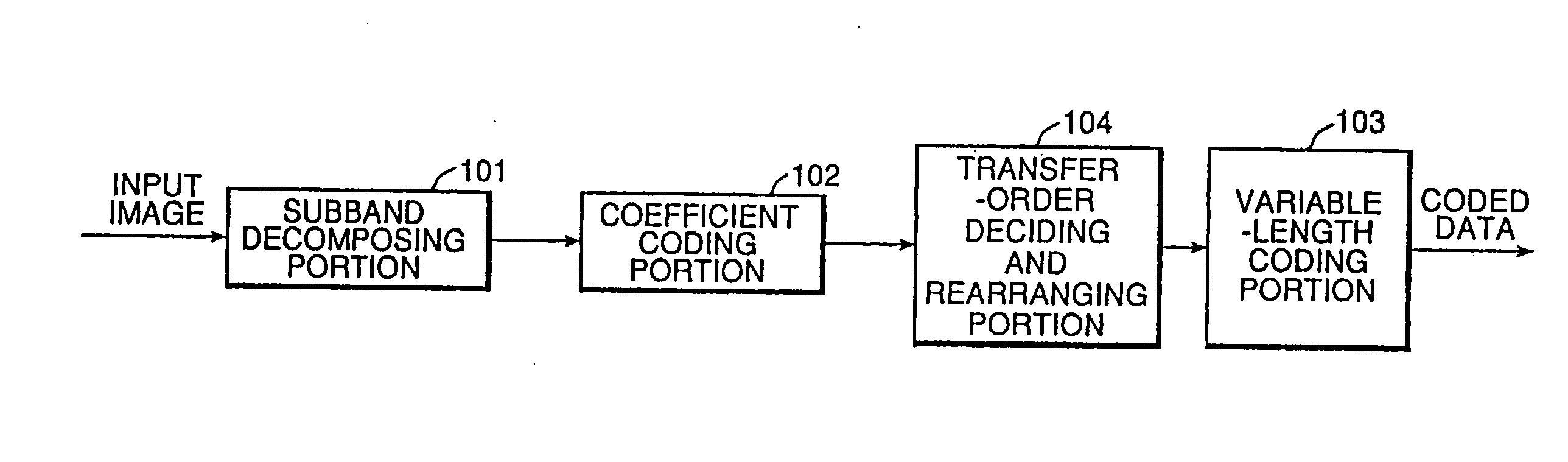
[0076] This makes it possible to conduct variable-length coding of the coded coefficient data by, e.g., an arithmetic coding method besides the Huffman coding method. According to the present invention, it is also possible to conduct rearrangement of the coded coefficient data after variable-length coding as the prior art device does. The operation of the first embodiment is described below with an input image composed of three components Y (luminance), U (chrominance) and V (chrominance), which is the same as that used in the prior art device. In this embodiment, these components have the same resolution, i.e., the same image sizes.

[0077] An integrated component unit may be prepared from coefficient-coded data by combining elements Y, U and V. The following example is an integrated component unit that is prepared of subbands of Y, U and V.

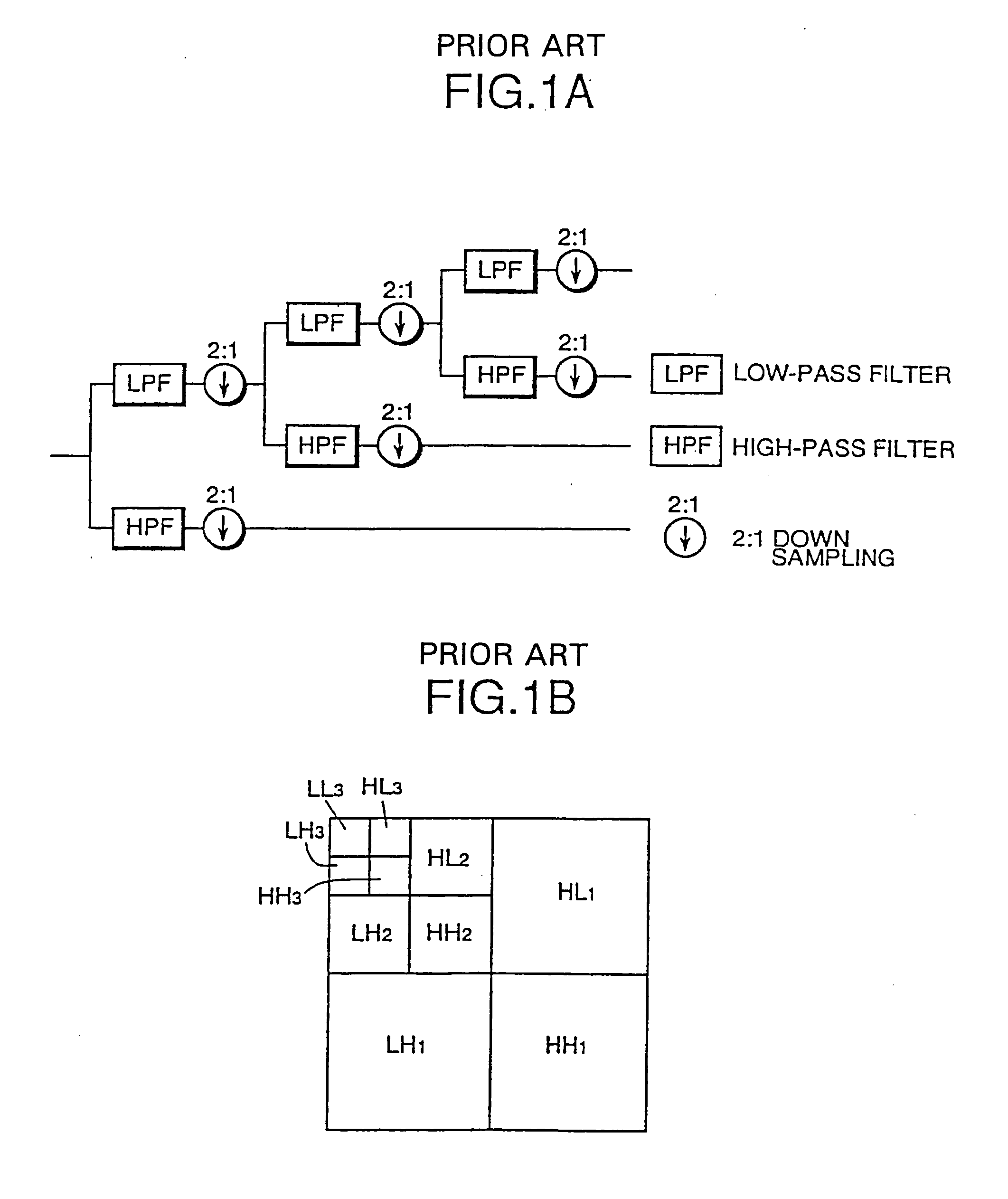
[0078]FIG. 9 shows coefficients of subband images obtained through performing three times of subband-decomposition of respective image component...

second embodiment

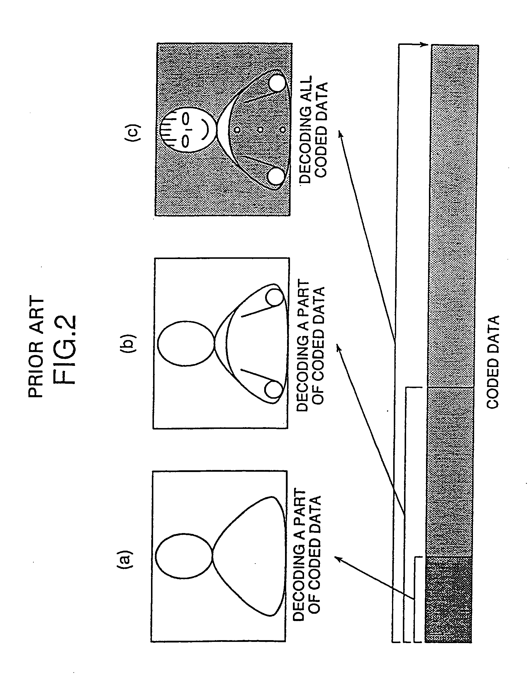
[0149] In the present invention, it is possible to give coded data a hierarchical structure even if components of an image have different sizes. The decoding side can decode entire decoded data and can also obtain an entire reproduced image from a part of the coded data.

[0150] Although the second embodiment has been described with only an image having components whose horizontal and vertical size ratio is 2:1:1, it can treat other size ratios of image components in the similar manner as described above.

[0151] A third embodiment of the present invention is adaptable to the case of processing image components being different in size and decomposed into different numbers of decomposition levels by the subband decomposing portion 101 of FIG. 7. This embodiment of the present invention is similar to the first embodiment except for the operation of the transfer-order deciding and rearranging portion 104 (step of outputting an integrated component unit). Therefore, the same portions are n...

third embodiment

[0176] In the present invention, an image whose components have different sizes and different decomposition levels can be encoded so that coded data having a hierarchical structure is obtained at the coding side and an entire image is reproduced from the entire coded data or a part of the coded data at the decoding side.

[0177] Although the third embodiment has been described by way of example with only an image having components whose size ratio is of 2:1:1, it can treat other size ratios of image components in the similar manner as described above. For example, an image whose components Y, U and V are the same in size and have different numbers of subbands can be encoded to have a hierarchical structure through the same process as described above in the third embodiment. The transmitting orders corresponding to those shown in FIGS. 11 and 13 are also adopted besides the described order of FIG. 10.

[0178] The three embodiments of the present invention have been described by way of e...


PUM


Abstract

A video coding device capable of adaptively processing input video data according to property of the data and realizing effective progressive transmission of the coded data even if image components are different in size and / or different in the number of subbands. The above-mentioned object can be realized by the provision of a transferring-order deciding and ranging portion that can prepare an integrated component unit by forming combinations of subband-based frequency-coefficients of respective components Y, U and V and can change the number of respective elements of respective components Y, U and V.

Description

TECHNICAL FIELD [0001] The present invention pertains to the field of digital video processing and relates to a video coding device for efficiently encoding video data and a video decoding device for decoding video data coded by the video coding device. BACKGROUND ART [0002] Recently, there has been proposed a subband coding method that can efficiently encode and decode video signals. The well-known high-efficient subband encoding method is used to decompose an input image into frequency bands by a bank of band-decomposing filters. The band-decomposing filter-bank is a one-dimensional filter-bank that can serve as a two-dimensional band-decomposing filter-bank by repeating processing the input image in horizontal and vertical directions. This method was reported by Fujii, Noumura. “Topics on Wavelet Transform” in a Report of “TECHNICAL REPORT of IEICE, IE92-11, 1992”. [0003] In the prior art, a subband image as shown in FIG. 1B obtained by conducting two-dimensional subband decompos...

Claims


Application Information

Patent Timeline
Patent Type & Authority Applications(United States)
IPC IPC(8): G06T9/00H04N1/41H04N11/04H04N19/00H04N19/33H04N19/423H04N19/436H04N19/46H04N19/60H04N19/635H04N19/70H04N19/91
CPCH04N11/042H04N19/13H04N19/63H04N19/36H04N19/61H04N19/186H04N19/64H04N19/129
Inventor AONO, TOMOKOSAIGA, HISASHIKATATA, HIROYUKIKUSAO, HIROSHI
Owner SHARP KK
Why Eureka
Try Eureka