
Single point modulator having a PLL circuit

a single-point modulator and circuit technology, applied in the field of single-point modulators, can solve the problems of requisite matching accuracy and complex circuitry of single-point modulators

Active Publication Date: 2005-02-03
APPLE INC
View PDF4 Cites 10 Cited by
  • Summary
  • Abstract
  • Description
  • Claims
  • Application Information

AI Technical Summary

Benefits of technology

The invention is a single-point modulator that can comply with the noise requirements of a spectral transmit mask. It includes a PLL circuit with a programmable frequency divider and a sigma-delta modulator with a digital filter. The digital filter has a transfer function that is designed to shape the quantization noise of the sigma-delta modulator. The invention also allows for the programmable filter coefficients to be set and controlled, which can adjust the transfer function of the digital filter and thus the noise transfer function of the sigma-delta modulator. The invention can be used in phase or frequency modulation.

Problems solved by technology

In this single-point modulator, the noise requirements mean that the bandwidth of the PLL control loop is designed to be considerably narrower than would actually be required for transmitting the modulated data.
The disadvantage of a single-point modulator of this type is the requisite matching accuracy between the digital filter for prefiltering the digital modulation data and the analogue loop filter which is usually provided in a PLL circuit.
The disadvantage of a two-point modulator is that its circuitry is more complex than that of a single-point modulator.

Method used


Image

  • Single point modulator having a PLL circuit
  • Single point modulator having a PLL circuit
  • Single point modulator having a PLL circuit

Examples


Embodiment Construction

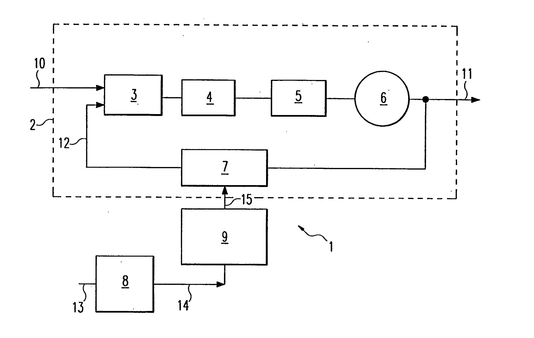
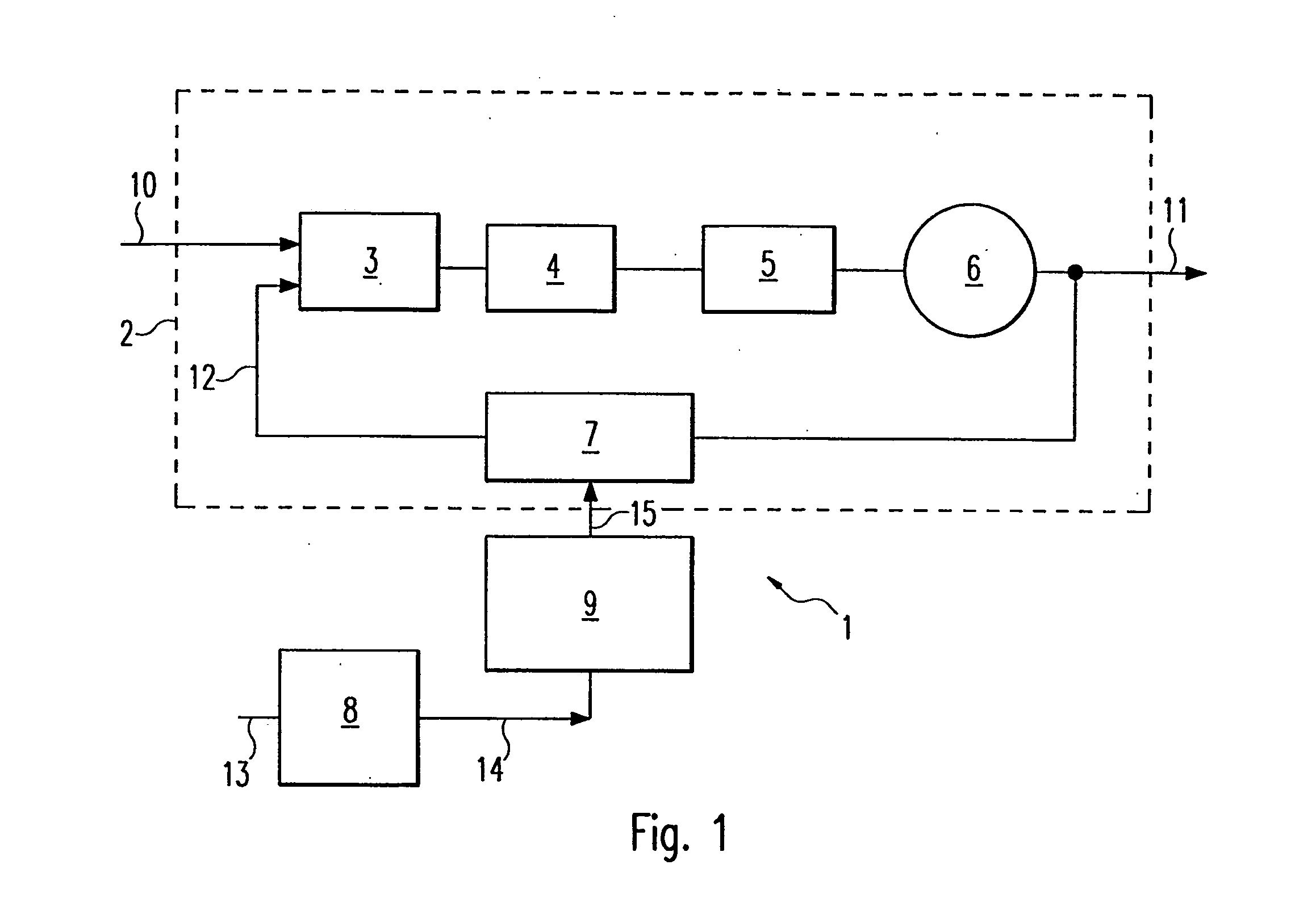
[0026]FIG. 1 shows a single-point modulator 1 having a PLL circuit 2 which uses an input or reference signal 10 at a reference frequency fref to produce an output signal 11 at an output frequency fout. The output signal 11 can be modulated by digital modulation data 15.

[0027] The PLL circuit 2 contains a phase frequency detector 3 whose inputs are supplied with the reference signal 10 and a frequency divider signal 12 which has been fed back. The reference signal 10 is derived, for example, from an oscillating crystal. The phase frequency detector 3 compares the phases of the two signals which are fed to its inputs and produces, at its output, a control signal corresponding to the phase difference between the reference signal 10 and the frequency divider signal 12. The control signal is fed into the input of a charge pump 4 which, as a function of the control signal, generates a current for charging a loop filter 5 connected downstream of the charge pump 4. The loop filter 5 contai...


PUM


Abstract

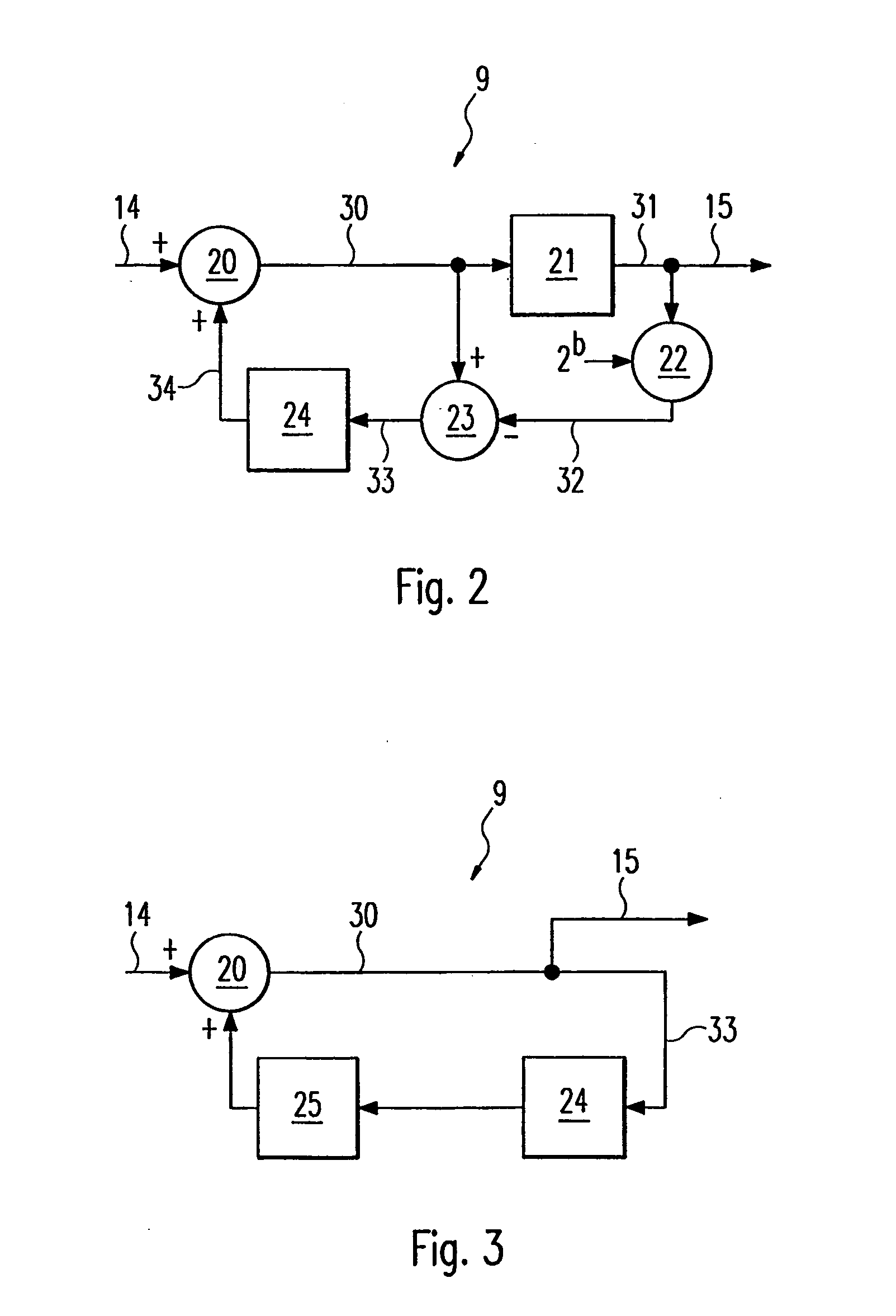
A single-point modulator (1) has a PLL circuit (2) and a programmable frequency divider (7) whose control connection is connected to a circuit branch for injecting a digital modulation signal (15) which is arranged in the feedback path of the PLL circuit (2). The circuit branch contains a sigma-delta modulator (9) which, in turn, has a digital filter (24) having a transfer function H(z). The noise transfer function NTF(z) of the sigma-delta modulator (9) is given by the function NTF(z)=1−H(z).

Description

CROSS REFERENCE TO RELATED APPLICATION [0001] This application is a continuation of copending International Application No. PCT / DE03 / 00146 filed Jan. 20, 2003 which designates the United States, and claims priority to German application no. 102 05 680.3 filed Feb. 12, 2002.TECHNICAL FIELD OF THE INVENTION [0002] The invention relates to a single-point modulator for phase or frequency modulation having a PLL circuit for injecting digital modulation data. BACKGROUND OF THE INVENTION [0003] A low-complexity implementation of a transmitter concept for transceivers in mobile radio systems is provided by transmitters having a modulator which operates on the known principle of single-point modulation. A PLL (phase locked loop) circuit is employed in this case as a frequency synthesizer and is used for phase or frequency modulation of a radio-frequency signal. [0004] In a single-point modulator, the digital modulation data is usually injected into the feedback path of the PLL circuit. The l...

Claims


Application Information

Patent Timeline
Patent Type & Authority Applications(United States)
IPC IPC(8): H03C3/09H03L7/197
CPCH03C3/0925H03L7/1976H03C3/0933
Inventor HAMMES, MARKUSPUMA, GIUSEPPE LIWAASEN, STEFAN VAN
Owner APPLE INC
Learn More