Fluid-Dynamic-Pressure Bearing, Spindle Motor Furnished with the Fluid-Dynamic-Pressure Bearing, Method of Manufacturing Rotor Assembly Applied in the Spindle Motor, and Recording-Disk Drive Furnished with the Spindle Motor

Active Publication Date: 2005-02-03
NIDEC CORP
View PDF7 Cites 53 Cited by
  • Summary
  • Abstract
  • Description
  • Claims
  • Application Information

AI Technical Summary

Benefits of technology

[0020] An object of the present invention is in a spindle motor furnished with a fluid-dynamic-pressure bearing to assure requisite bearing stiffness in the radial and thrust bearing sections, precision in the right-

Problems solved by technology

Consequently, scaling down and reducing the profile of a spindle motor as described earlier while sustaining the rotational precision called for in the motor proves to be extraordinarily challenging.
The fact that, as is well known, the viscosity of oil drops under high-temperature environments means that the dynamic pressure generated by oil-filled dynamic-pressure bearings in such environments also falls, which consequently is prohibitive of attaining predetermined bearing stiffness.
Employing a highly viscous oil in order to avert such degradation in oil viscosity means that the oil will be excessively viscous under low-temperature environments, increasing the rotational load on the motor, such that ultimately the amount of power that the motor consumes will grow.
If escaped oil adheres to the hard disks in the disk-drive area, or to the magnetic heads arranged in close proximity to the disks, the oil will become a cause that gives rise to read/writ

Method used


Image

  • Fluid-Dynamic-Pressure Bearing, Spindle Motor Furnished with the Fluid-Dynamic-Pressure Bearing, Method of Manufacturing Rotor Assembly Applied in the Spindle Motor, and Recording-Disk Drive Furnished with the Spindle Motor
  • Fluid-Dynamic-Pressure Bearing, Spindle Motor Furnished with the Fluid-Dynamic-Pressure Bearing, Method of Manufacturing Rotor Assembly Applied in the Spindle Motor, and Recording-Disk Drive Furnished with the Spindle Motor
  • Fluid-Dynamic-Pressure Bearing, Spindle Motor Furnished with the Fluid-Dynamic-Pressure Bearing, Method of Manufacturing Rotor Assembly Applied in the Spindle Motor, and Recording-Disk Drive Furnished with the Spindle Motor

Examples


Embodiment Construction

[0032] Below, a fluid-dynamic-pressure bearing involving the present invention, a spindle motor furnished with the fluid-dynamic-pressure bearing, and a recording-disk drive furnished with the spindle motor will be explained with reference to FIGS. 1 through 5. It should be understood that in the embodiments illustrating the present invention, for the sake of convenience the upward and downward orientations in the drawings are rendered “upper / lower,”“top / bottom,”“along the vertical,” etc., but that is not intended to limit the orientation of the bearing, motor, and disk drive of the invention in an actually installed situation.

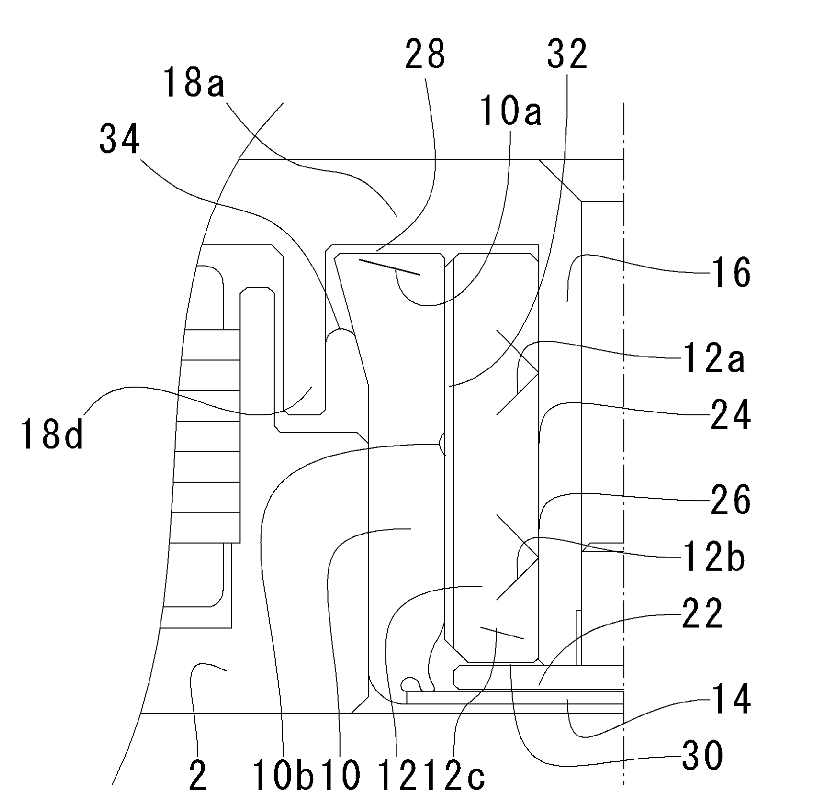
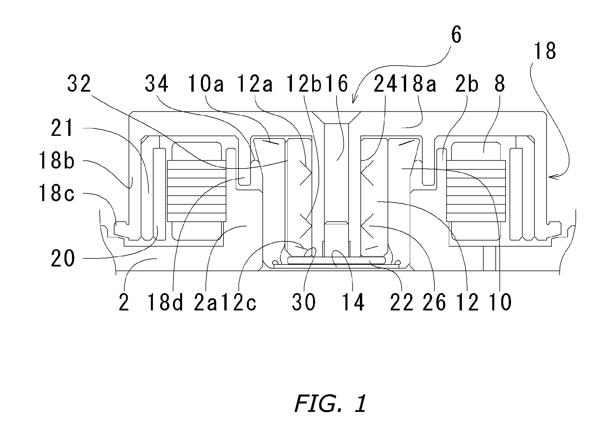
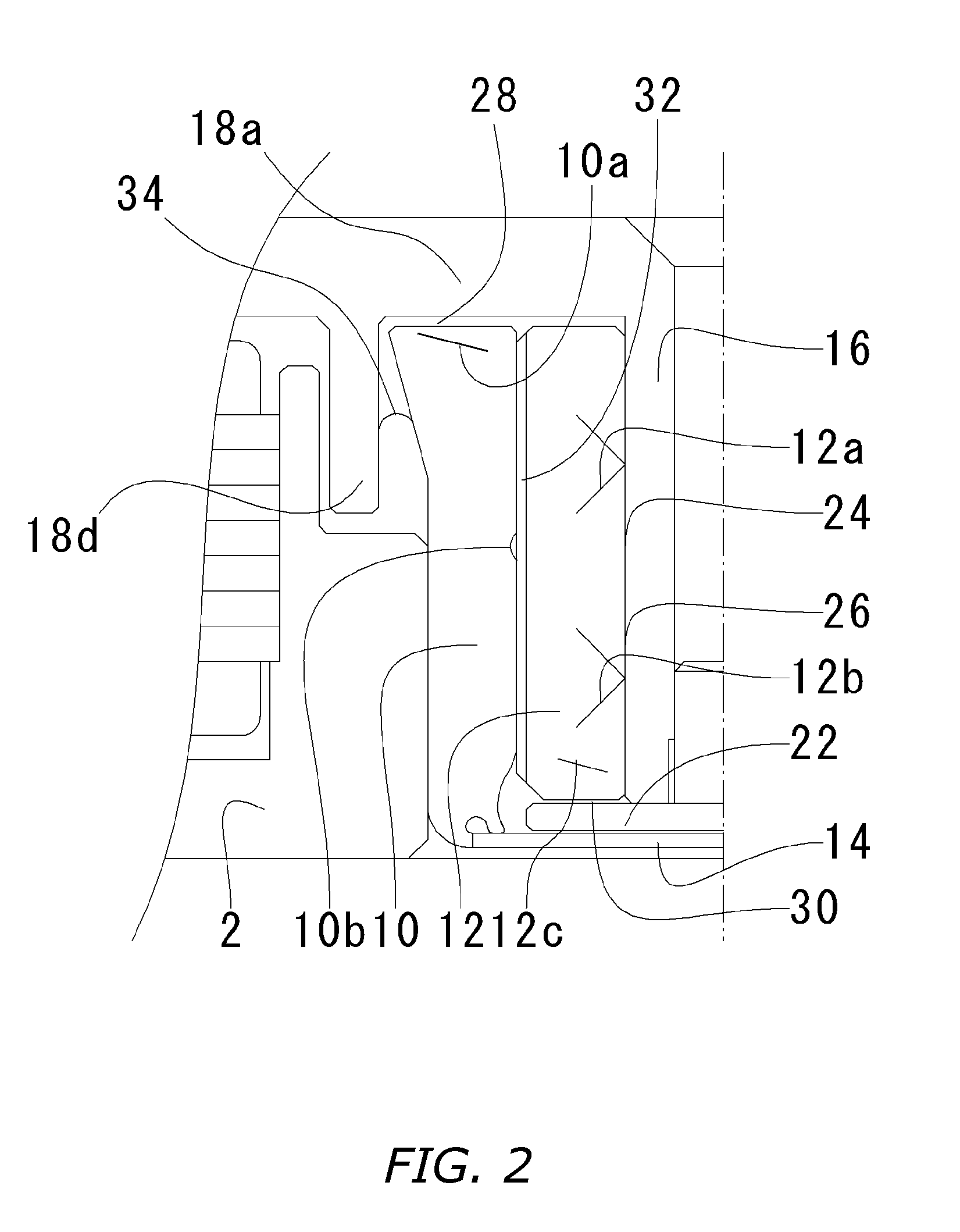
[0033] A spindle motor involving the present embodiment is basically composed of, as depicted in FIG. 1: a bracket 2; a bearing housing 10 fixed into the bracket 2; a sleeve 12 fixed to the cylindrical inner periphery of the bearing housing 10; and a rotor 6 rotatively supported by means of the sleeve 12.

[0034] An annular boss 2a encompassing a center hole i...


PUM

PropertyMeasurementUnit
Pressureaaaaaaaaaa
Dimensionaaaaaaaaaa
Deformation enthalpyaaaaaaaaaa

Abstract

Fluid-dynamic-pressure bearing furnished with a shaft, a top plate fixed to an upper portion of the shaft, a thrust plate fixed to a lower portion of the shaft, a sleeve, and a cuplike bearing housing that along its inner periphery retains the sleeve. A lubricating-fluid-filled continuous micro-gap is formed in between the shaft and the sleeve and the top plate and the sleeve. Radial bearing sections are formed in between the shaft cylindrical outer surface and the sleeve cylindrical inner surface. An upper thrust bearing section is formed in between the undersurface of the top plate and the top-edge face of the bearing housing. A lower thrust bearing section formed in between the bottom margin of the sleeve and the top margin of the thrust plate. The bearing sections are each provided with dynamic-pressure-generating grooves for inducing dynamic pressure in the lubricating fluid when the shaft or sleeve spins.

Description

BACKGROUND OF INVENTION [0001] 1. Technical Field [0002] The present invention relates to fluid-dynamic-pressure bearings and spindle motors furnished with the fluid-dynamic-pressure bearings, to methods of manufacturing rotor assemblies applied in the spindle motors, and to recording-disk drives furnished with the spindle motors. [0003] 2. Background Art [0004] As bearings for motors that drive recording disks in hard disk drives, removable disk drives and similar devices, to date fluid-dynamic-pressure bearings have been employed and a variety have been proposed. Fluid-dynamic-pressure bearings exploit dynamic pressure generated, when the motor spins, in a lubricating fluid such as oil retained in a gap in between, as for example shown in FIG. 6, a shaft 102 and a sleeve 104. [0005] In a conventional motor such as is depicted in FIG. 6, a pair of radial bearing sections 106 provided at an axial separation is formed in the gap in between the cylindrical outer surface of the shaft 1...

Claims


Application Information

Patent Timeline
IPC IPC(8): F16C17/10F16C17/02F16C17/04F16C33/10F16C43/02G11B19/20H02K5/16H02K7/08
CPCF16C17/107F16C33/107F16C43/02Y10T29/49639H02K5/1675F16C2370/12G11B19/2018F16C2240/40
Inventor TAMAOKA, TAKEHITO
Owner NIDEC CORP
Why Eureka
Try Eureka