Polysilicon line having a metal silicide region enabling linewidth scaling

a polysilicon line and metal silicide technology, applied in the field of polysilicon lines, can solve the problems of affecting the electrical resistance of conductive lines and contact regions, and reducing the cross-sectional area of these lines and regions

Active Publication Date: 2005-02-03
ADVANCED MICRO DEVICES INC
View PDF7 Cites 28 Cited by
  • Summary
  • Abstract
  • Description
  • Claims
  • Application Information

AI Technical Summary

Benefits of technology

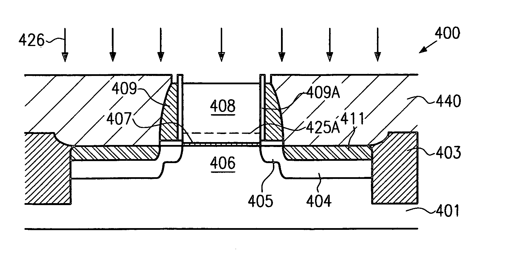
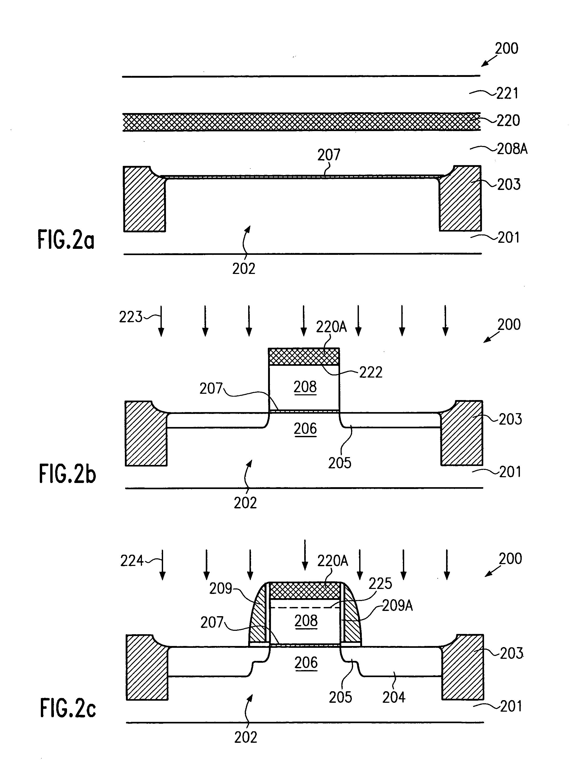
[0021] According to still a further illustrative embodiment of the present invention, a method of forming a field effect transistor comprises forming a layer stack including at least a gate insulation layer, a polysilicon layer and a cap layer above a silicon region formed on a substrate. The layer stack is then patterned so as to form a gate electrode having a top surface covered at least by the cap layer. Then, drain and source regions are formed adjacent to the gate electrode and silicide regions comprising a first metal are formed in the drain and source regions. After forming the metal silicide regions with the first metal, the gate electrode is dope...

Problems solved by technology

Shrinking the feature sizes, however, entails certain problems that may partially offset the advantages obtained by reducing the feature sizes.
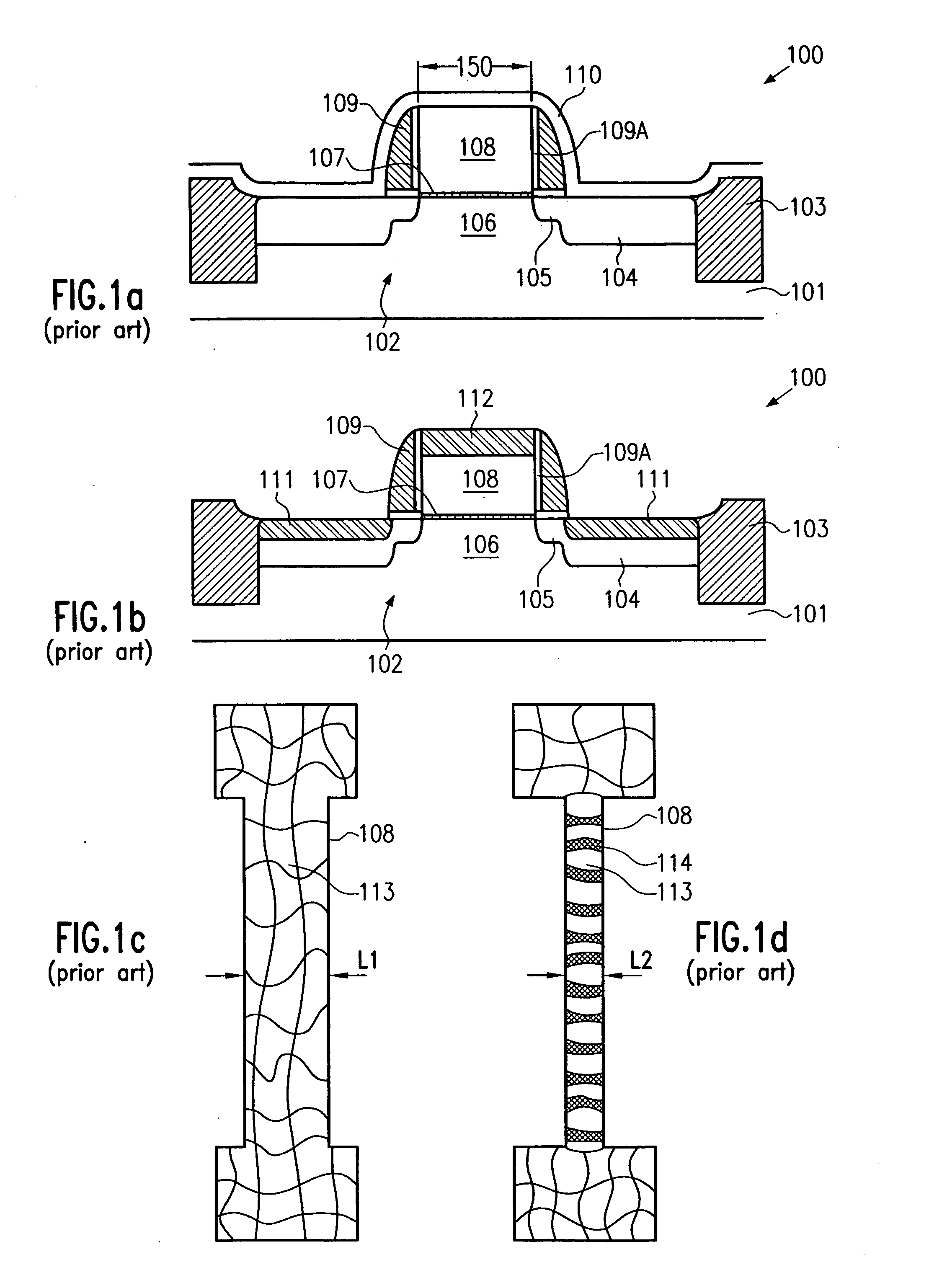
Upon decreasing the channel length of the transistor elements, however, the electrical resistance of conductive lines and contact regions, i.e., of regions that provide electrical contact to the periphery of the transistor elements, becomes a major issue since the cross-sectional area of these lines and regions is also reduced.
Moreover, a higher number of circuit elements per unit area also requires an increased number of interconnections between these circuit elements, wherein, commonly, the number of required interconnects increases in a non-linear manner with the number of circuit elements so that the available real estate for interconnects becomes even more limited.
Although reducing the feature size of a transistor element improves device performance due to the reduced channel length, the shrink...

Method used


Image

  • Polysilicon line having a metal silicide region enabling linewidth scaling
  • Polysilicon line having a metal silicide region enabling linewidth scaling
  • Polysilicon line having a metal silicide region enabling linewidth scaling

Examples


Embodiment Construction

[0030] Illustrative embodiments of the invention are described below. In the interest of clarity, not all features of an actual implementation are described in this specification. It will of course be appreciated that in the development of any such actual embodiment, numerous implementation-specific decisions must be made to achieve the developers' specific goals, such as compliance with system-related and business-related constraints, which will vary from one implementation to another. Moreover, it will be appreciated that such a development effort might be complex and time-consuming, but would nevertheless be a routine undertaking for those of ordinary skill in the art having the benefit of this disclosure.

[0031] The present invention will now be described with reference to the attached figures. Although the various regions and structures of a semiconductor device are depicted in the drawings as having very precise, sharp configurations and profiles, those skilled in the art reco...


PUM


Abstract

By maintaining the gate electrode covered during the process flow for forming metal silicide regions in the drain and source of a field effect transistor, an appropriate metal silicide may be formed on the gate electrode which meets the requirement for aggressive gate length scaling. Preferably, a nickel silicide is formed on the gate electrode, whereas the drain and source regions receive the well-established cobalt disilicide. Additionally, the gate electrode dopant profile is effectively decoupled from the drain and source dopant profile.

Description

BACKGROUND OF THE INVENTION [0001] 1. Field of the Invention [0002] Generally, the present invention relates to the fabrication of integrated circuits, and, more particularly, to the formation of metal silicide regions on silicon-containing conductive circuit elements to decrease a sheet resistance thereof. [0003] 2. Description of the Related Art [0004] In modern ultrahigh density integrated circuits, device features are steadily decreasing to enhance device performance and functionality of the circuit. Shrinking the feature sizes, however, entails certain problems that may partially offset the advantages obtained by reducing the feature sizes. Generally, reducing the size of, for example, a transistor element such as a MOS transistor, may lead to superior performance characteristics due to a decreased channel length of the transistor element, resulting in a higher drive current capability and enhanced switching speed. Upon decreasing the channel length of the transistor elements, ...

Claims


Application Information

Patent Timeline
IPC IPC(8): H01L21/28H01L21/285H01L21/3205H01L21/336H01L21/4763H01L29/78
CPCH01L21/28052H01L21/28518H01L29/7833H01L29/66545H01L29/6656H01L29/66507
Inventor KAMMLER, THORSTENWIECZOREK, KARSTENSCHALLER, MATTHIAS
Owner ADVANCED MICRO DEVICES INC
Why Eureka
Try Eureka