Fuel dispenser fuel flow meter device, system and method

a technology of fuel flow meter and fuel dispenser, which is applied in the direction of liquid transfer device, liquid/fluent solid measurement, instruments, etc., can solve the problems of inaccurate fuel price and the number of gallons dispensed

Active Publication Date: 2005-02-10
GILBARCO +1
View PDF37 Cites 34 Cited by
  • Summary
  • Abstract
  • Description
  • Claims
  • Application Information

AI Technical Summary

Benefits of technology

[0013] The dual piston/poppet valve operates in one of three modes. The first mode is the fully closed mode where both pistons are closed and no fuel flows through the valve. The second mode is a slow flow open mode. In this mode, a secondary or bypass fuel path is open and fuel flows relatively slowly through the valve. The indicator, if present, tells the control system that the bypass fuel path is open and thus, the control system knows to accept inputs from the flow meter as non-spurious. The third mode is a high flow open mode. In

Problems solved by technology

This will cause the number of gallons dispensed as well as the

Method used


Image

  • Fuel dispenser fuel flow meter device, system and method
  • Fuel dispenser fuel flow meter device, system and method
  • Fuel dispenser fuel flow meter device, system and method

Examples


Embodiment Construction

[0036] The embodiments set forth below represent the necessary information to enable those skilled in the art to practice the invention and illustrate the best mode of practicing the invention. Upon reading the following description in light of the accompanying drawing figures, those skilled in the art will understand the concepts of the invention and will recognize applications of these concepts not particularly addressed herein. It should be understood that these concepts and applications fall within the scope of the disclosure and the accompanying claims.

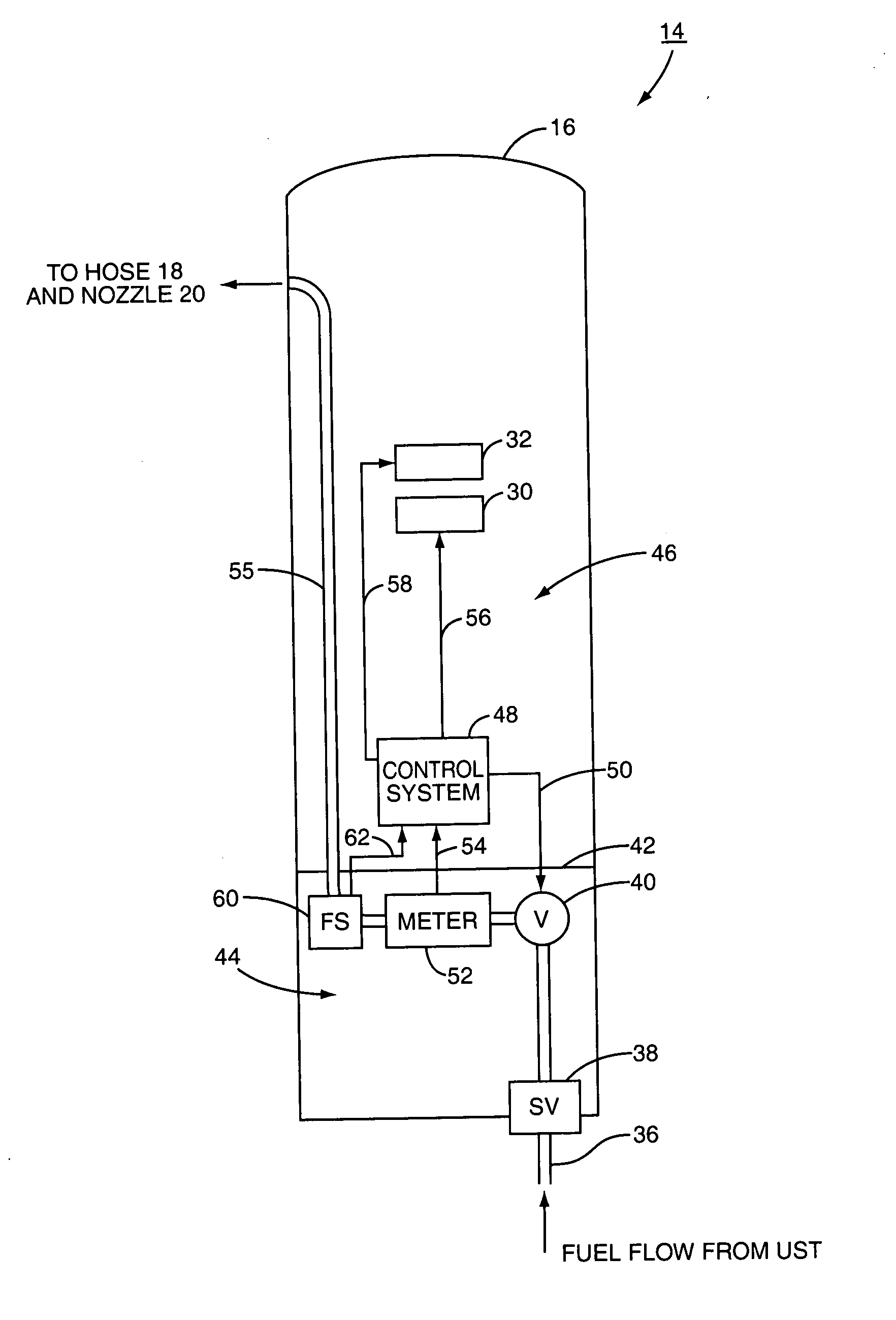
[0037] The present invention is directed to a flow switch that operates in a fuel dispenser to detect and communicate when fuel is flowing in the fuel dispenser and being delivered to a vehicle. For certain types of fuel flow meters used in fuel dispensers, the flow meter may continue to indicate a signal or indicia indicative of fuel flow after fuel flow has stopped. In this manner, a fuel dispenser will continue to operate as ...


PUM


Abstract

A flow switch used on conjunction with a fuel flow meter in a fuel dispenser to determine when fuel flow rate signals form a fuel flow meter should be ignored in the calculation of flow rate and/or volume of fuel dispensed. An inferential fuel flow meter may be used as the fuel flow meter. The inferential fuel flow meter may be a turbine flow meter that comprises one or more turbine rotors that rotate in response to fuel flow flowing through the turbine flow meter. The turbine rotors may continue to generate pulses even when fuel is no longer flowing. A flow switch determines when fuel is actually flowing and fuel is not actually flowing. The flow switch is described as either a single poppet or dual poppet flow switch in examples described herein.

Description

FIELD OF THE INVENTION [0001] The present invention relates to a device, system and method for determining accurately the volume of fuel flow dispensed by a fuel dispenser. BACKGROUND OF THE INVENTION [0002] In a typical transaction, a consumer may drive a vehicle up to a fuel dispenser in a fueling environment. The consumer arranges for payment, either by paying at the pump, paying the cashier with cash, using a credit card or debit card, or some combination of these methods. The nozzle is inserted into the fill neck of the vehicle, and fuel is dispensed into the gas tank of the vehicle. Displays on the fuel dispenser display how much fuel has been dispensed as well as a dollar value associated with the fuel that has been dispensed. The customer relies on the fuel dispenser to measure the amount of fuel dispensed accurately and charge the customer accordingly. One method customers sometimes use to control costs is to pay for a preset amount of fuel based on a dollar or volume amoun...

Claims


Application Information

Patent Timeline
IPC IPC(8): B67D7/08B67D7/20B67D7/56F16K37/00G01F1/12
CPCB67D7/20B67D7/565F16K37/0033F16K37/005F16K37/0091F16K37/0083F16K37/0041G01F1/12
Inventor OLIVIER, PAUL D.SHERMER, WILLIAM P.NANAJI, SEIFOLLAH S.
Owner GILBARCO
Why Eureka
Try Eureka