Signal transmission cable terminal device and data transmission method using signal transmission cable

a technology of signal transmission cable and terminal device, which is applied in the direction of insulated conductors, power cables, cables, etc., can solve the problems of not being able to achieve the mechanical strength and signal propagation performance of the cable, and the finish outer shape of the cable was as thick as 4.8 mm, so as to achieve high flexing properties, reduce the occupied area, and high mechanical strength

Inactive Publication Date: 2005-02-10
SUMITOMO ELECTRIC IND LTD
View PDF1 Cites 27 Cited by
  • Summary
  • Abstract
  • Description
  • Claims
  • Application Information

AI Technical Summary

Benefits of technology

[0061] In this transmission method, almost the same broadband performance as obtained in a transmission method, using the current products, can be se

Problems solved by technology

However, when the individual constituent elements were merely reduced in size or diameter so as to reduce the cable diameter, there was encountered a problem that the cable, sufficiently satisfactory in both mechanical strength and signal propagation p

Method used


Image

  • Signal transmission cable terminal device and data transmission method using signal transmission cable
  • Signal transmission cable terminal device and data transmission method using signal transmission cable
  • Signal transmission cable terminal device and data transmission method using signal transmission cable

Examples


first embodiment

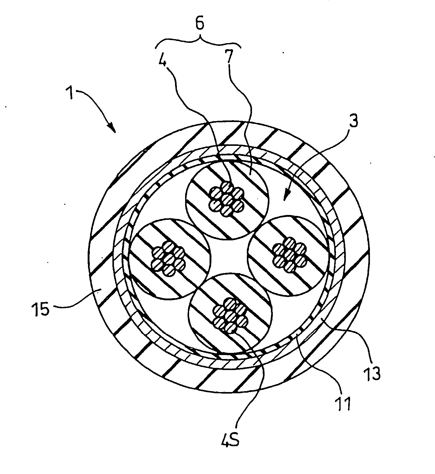
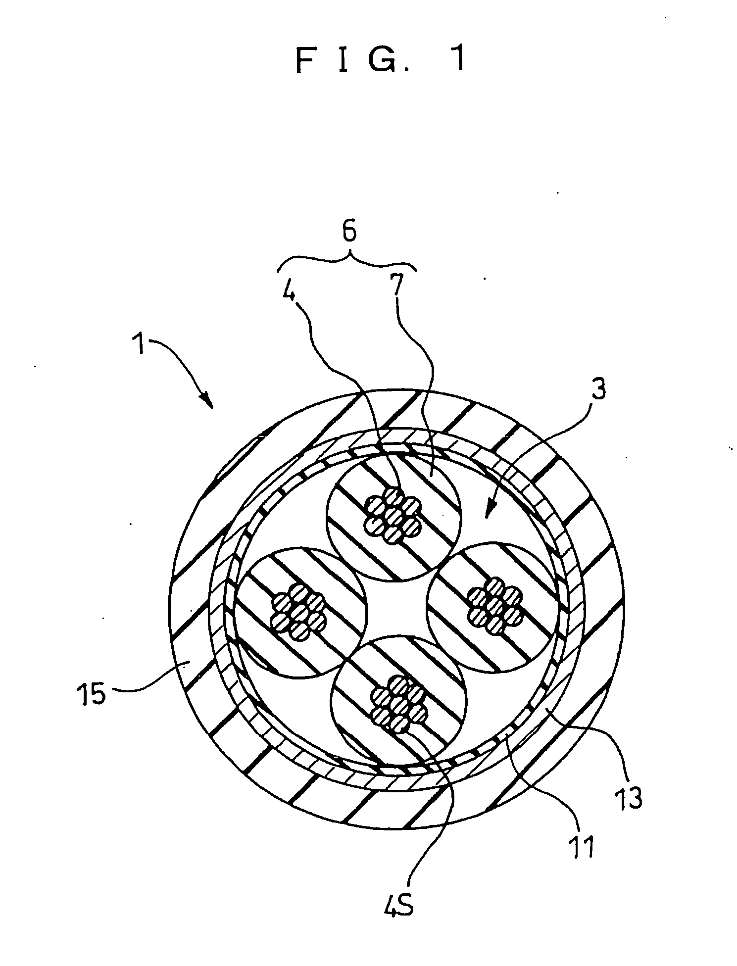
[0072] As shown in FIG. 1, a signal transmission cable 1 of the present invention is formed by twisting four insulated wires 6 (each comprising an insulation-coated center conductor) together to form a quad-structure wire 3, by covering its outer surface with an insulating tape 11 or a metallic tape, and further by covering it with an outer shielding member comprising a wire mesh 13, and an outer diameter of this cable is not larger than 3 mm. Here, the center conductor is formed by twisting 7 center conductor wires 4 together. Then, it is covered at its outer surface with an insulating coating layer 7 composed of a fluororesin, polyethylene, foamed polyethylene, thereby forming the insulated wire 6. In order that this signal transmission cable 1 can satisfy specified values of attenuation and mechanical strength with a cable length of 2.5 m, this signal transmission cable is characterized in that a conductor diameter of the center conductor, forming the insulated wire 6, is reduced...

second embodiment

[0107] Next, the present invention will be described.

[0108] This example is characterized in that a metallic tape 12 is used instead of the insulating tape 11 covering the quad-structure wire 3, as shown in FIG. 6.

[0109] The other portions are formed in the same manner as described above for the first embodiment.

[0110] This metallic tape 12 comprises an aluminum-bonded polyester tape having a thickness of 0.015 mm, and as in the signal transmission cable of the first embodiment, good electrical characteristics and mechanical characteristics can be maintained with a small outer diameter.

[0111] In the case of using the metallic tape, unnecessary radiation (EMI: Electromagnetic Interference) noises can be reduced as compared with the case where the insulating tape is used.


PUM


Abstract

It is intended to provide a high-speed differential signal cable having a small diameter and high strength. A 4-conductor cable includes four insulation-coated insulated wires (center conductors) bundled together, and a wire mesh and an insulating sheath which cover a periphery thereof, and this cable is characterized in that a conductor size of center conductor wires is thinned so as to satisfy a specified value of attenuation with a cable length of 2.5 m, and also twisted pair wires are replaced by a quad-structure wire, so that the outer diameter is not larger than 3 mm.

Description

TECHNICAL FIELD [0001] This invention relates to a signal transmission cable, a terminal apparatus and a data transmission method using a signal transmission cable, and more particularly to the structure of a high-speed differential signal cable with small-diameter and high-strength characteristics used in the case where the supply of electric power is not needed in a high-speed serial interface (called IEEE1394) used to connect a computer to its peripheral device. BACKGROUND ART [0002] In IEEE1394, there have been used “IEEE1394-1995 Standard” as shown in FIG. 7 in which the supply of electric power is conducted and “Standard for a High Performance Serial Bus (Amendment 1) (hereinafter referred to as “Amendment 1 of the IEEE1394-1395 Standard”) as shown in FIG. 8 in which the supply of electric power is not conducted. This is based on the assumption that the maximum cable length of IEEE1394 is 4.5 m. [0003] As shown in FIG. 8, a cable structure of this Amendment 1 is formed by furt...

Claims


Application Information

Patent Timeline
IPC IPC(8): H01B11/00H01B11/02H01B11/04H01B11/10
CPCH01B11/005H01B11/1033H01B11/10
Inventor TAKAHASHI, HIROKAZUTSUJINO, ATSUSHIYOKOI, KIYONORIOOTSUKA, HIROYUKI
Owner SUMITOMO ELECTRIC IND LTD
Why Eureka
Try Eureka