Vibration suppression device of power train

Inactive Publication Date: 2005-02-10
MAZDA MOTOR
View PDF13 Cites 3 Cited by
  • Summary
  • Abstract
  • Description
  • Claims
  • Application Information

AI Technical Summary

Benefits of technology

[0007] The present invention has been devised in view of the above-described problems, and an object of the present invention is to provide a vibration suppression device

Problems solved by technology

As a result, there may occur a problem that such vibration transfers to the vehicle body and causes a heavy noise generating in a vehicle compartment.
As a result, there is a problem that the vibration of the transfer and/or the power train may not be suppressed properly.
Further, in the case where there is newly provided the dynamic damper

Method used


Image

  • Vibration suppression device of power train
  • Vibration suppression device of power train
  • Vibration suppression device of power train

Examples


Example

[0036] Hereinafter, a power train of a four-wheel drive vehicle according to a preferred embodiment of the present invention will be described.

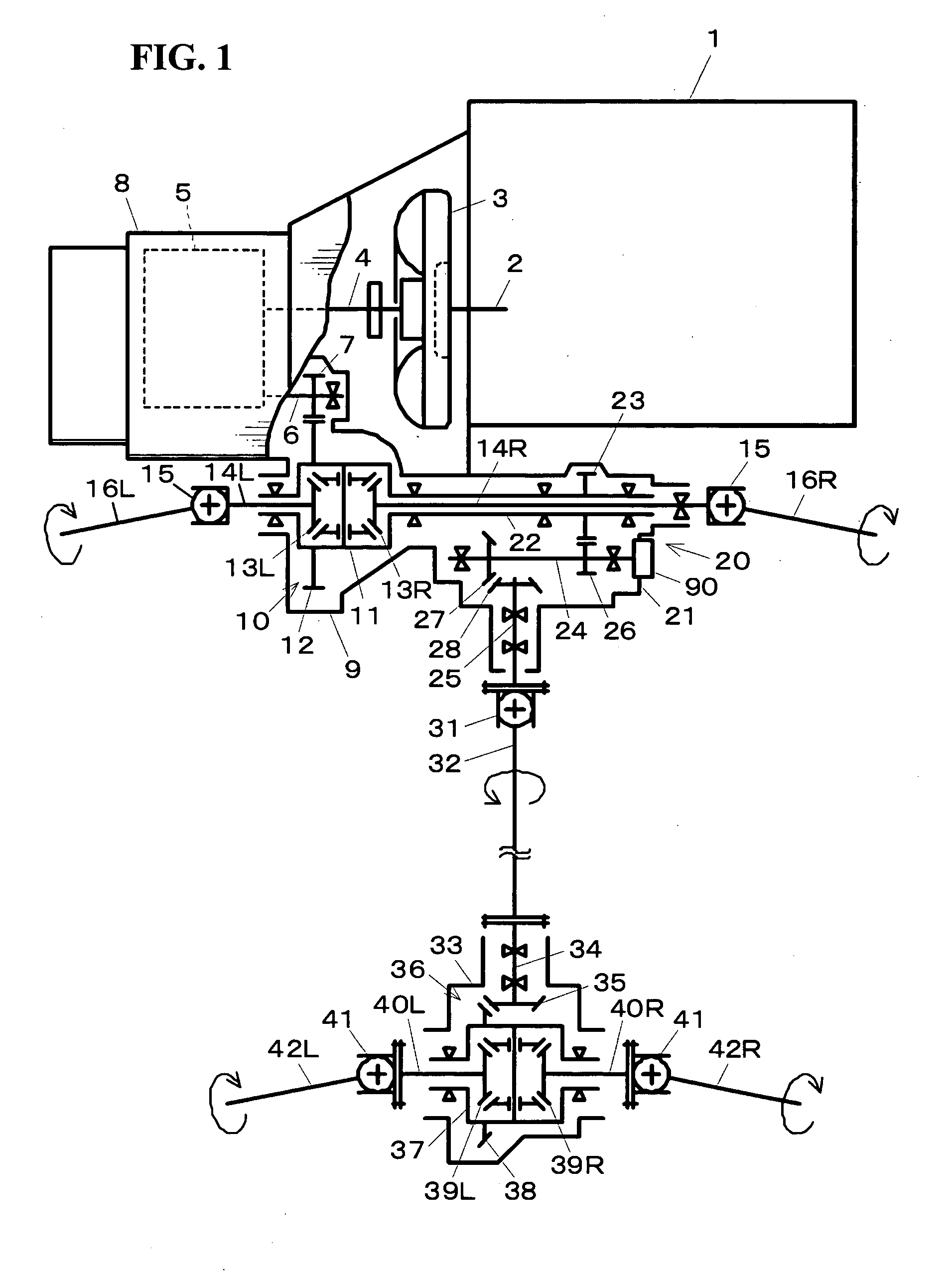
[0037] As shown in FIG. 1, this four-wheel drive vehicle is a vehicle whose engine 1 is disposed in a vehicle width direction in an engine room which is provided at a front side of a vehicle body. Herein, a crankshaft 2 of the engine 1 extends in the vehicle width direction, a torque converter 3 is coupled to the crankshaft 2, and a transmission 5 is coupled to a turbine shaft 4 of the torque converter 3. An output shaft 6 of the transmission 5 also extends in the vehicle width direction and is provided with an output gear 7.

[0038] The above-described torque converter 3 and the transmission 5 are stored in a case 8 which is coupled to the engine 1. The case 8 is provided with a front-differential storage portion 9 which extends backward, and a front differential 10 is stored in the storage portion 9.

[0039] The front differential 10 compris...


PUM


Abstract

A heat exchanger, which performs heat exchanging between a lubricating oil circulating within a transfer device disposed behind an engine and an engine coolant, also functions as a mass member of a dynamic dumper. The heat exchanger is disposed at an upper face of a transfer case via a resilient member. Herein, the resilient member is comprised of a first metal plate, a second metal plate, and a rubber member interposed between the first and second metal plates, and there are provided lubricating passages flowing within the resilient member. Accordingly, there can be provided the vibration suppression device of the power train that can suppress vibration properly regardless of the temperature changing and advantage the weight reduction without requiring any new disposition space.

Description

BACKGROUND OF THE INVENTION [0001] The present invention relates to a vibration suppression device of a power train including an engine mounted on a vehicle body and belongs to a technical field of a vibration suppression of a motor vehicle. [0002] A four-wheel drive vehicle is normally equipped with a transfer device to transfer an engine power derived from an engine to front and rear wheels respectively. The transfer device of the four-wheel drive vehicle whose engine is disposed in a vehicle width direction generally comprises an input shaft extending in the vehicle width direction and inputting the engine power from a front engine via a transmission, an output shaft extending backward of the vehicle with crossing the input shaft at a right angle, a bevel gear provided between the input and output shafts, and a case storing these shafts and bevel gear and including a journal to support the above-described output shaft. [0003] In such a structure where the transfer device as a mas...

Claims


Application Information

Patent Timeline
IPC IPC(8): F16F7/108F16F15/02
CPCF16F7/108F16F2230/04Y10T74/2189F16H57/0483Y10S165/916F16H57/0415
Inventor YAMAMOTO, KOICHIOHKAWA, YUZOUMITO, EIJI
Owner MAZDA MOTOR
Why Eureka
Try Eureka