Grease interceptor (trap) and servicing method

a technology of traps and refuse tanks, applied in separation processes, liquid displacement, filtration separation, etc., can solve the problems of generating great hardship for those maintaining city wide infrastructure, excess waste can damage filtration and waste processing plants, and restaurant and other commercial venues generate large amounts of waste. , to achieve the effect of greatly simplifying the installation of indoors

Inactive Publication Date: 2005-02-10
RODIS NANCY JEANNINE
View PDF21 Cites 8 Cited by
  • Summary
  • Abstract
  • Description
  • Claims
  • Application Information

AI Technical Summary

Benefits of technology

[0013] A grease interceptor (trap) and management tank is disclosed herein. The trap has two compartments, a forward and rear compartment separated by two baffles so that grease and oils may rise and solids and sludge settle out and not be introduced into a sewer line. An ultra sonic monitoring device is also shown with local record keeping and alarm capabilities as well as remote management options through phone line, wireless or internet communications. Servicing may be scheduled accord

Problems solved by technology

Restaurants and other commercial venues generate large amounts of waste that is disposed of down a drain.
The grease, soap and semi-solids that are then introduced into the sewer system, may generate great hardship for those maintaining a city wide infrastructure.
The excess waste can damage filtration and waste processing plants, as well as clog and damage pipes in the field.
Also, if no such solution is used, clogs may back up a sewer, producing a sanitary sewer overflow.
To combat this problem, many localities regulate how much effluent and waste a restaurant or other commercial venue may dispose of throu

Method used


Image

  • Grease interceptor (trap) and servicing method
  • Grease interceptor (trap) and servicing method
  • Grease interceptor (trap) and servicing method

Examples


Embodiment Construction

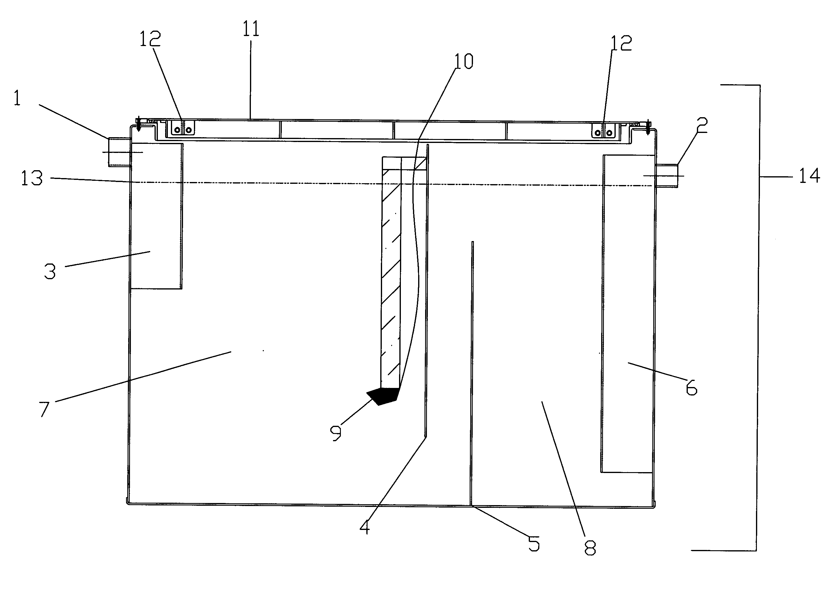
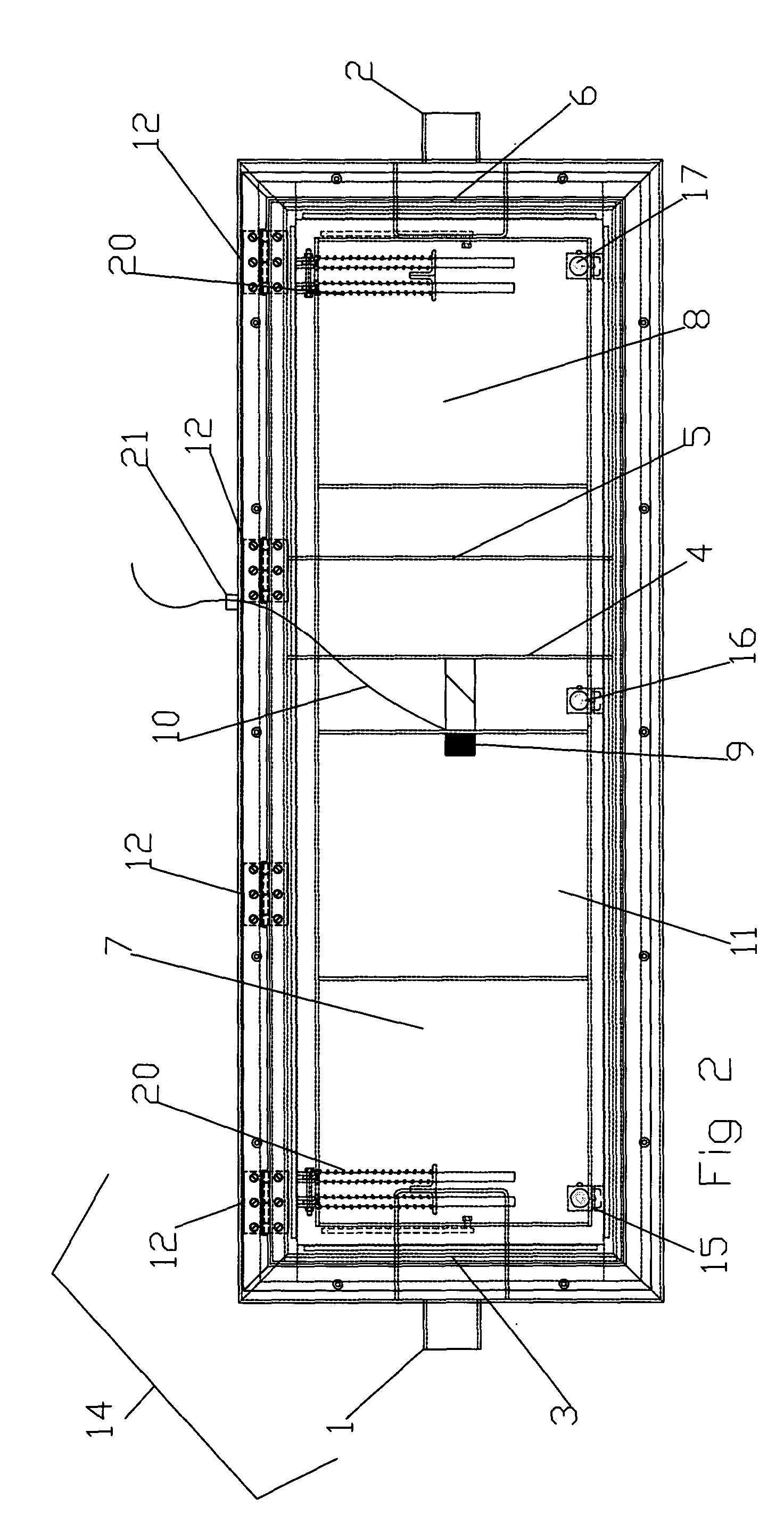
[0020] Referring now to the drawings, and more particularly to FIG. 1, the grease trap (also referred to as a refuse tank) 14 is shown in its preferred embodiment. Water and effluent enters the grease trap 14 through intake pipe 1 and enters the first compartment 7. Material introduced to the tank 7 by pipe 1 is guided by duct 3 so the water and effluent are introduced in the middle level of the first compartment 7 of the grease trap 14. The usual level of the contents of the entire grease trap 14 is denoted by line 13. It is to this level that grease and oils will rise, while semi-solids and other wastes may fall to the bottom of the first compartment 7. In this compartment 7, most of the waste is trapped.

[0021] To assist in monitoring the levels of the waste, it is preferable that an ultrasonic monitor 9 is used. Ultrasonic monitor 9 emits high frequency sound waves both upwards and downwards. By measuring the amount of time it takes any reflected sound waves to return to the mon...


PUM

PropertyMeasurementUnit
Lengthaaaaaaaaaa
Lengthaaaaaaaaaa
Volumeaaaaaaaaaa

Abstract

A grease trap and management tank is disclosed herein. The trap has two compartments, a forward and rear compartment separated by two baffles so that grease and oils may rise and solids and sludge settle out and not be introduced into a sewer line. An ultra sonic monitoring device is also shown with local record keeping and alarm capabilities as well as remote management options through phone line, wireless or internet communications. Servicing may be scheduled according to this data to prevent any problems with the trap. The grease trap also features an access door that opens to reveal the entirety of the grease trap for easy cleaning. Since the dimensions of the tank do not exceed the width and height of standard doorways, installation indoors is greatly simplified. Along with adaptable risers, the trap may be made of metal, plastic or any other suitable material, installed indoors and mounted in concrete or any other suitable construction material.

Description

[0001] This application claims priority to U.S. Provisional Application 406,516 filed Aug. 28, 2002BACKGROUND OF THE INVENTION [0002] 1. Field of the Invention [0003] The present invention generally relates to grease traps and refuse tanks and methods of servicing grease traps and refuse tanks. More particularly, the invention offers solutions for the construction and positioning of large grease traps, as well as monitoring and servicing of large grease traps. [0004] 2. Background Description [0005] Restaurants and other commercial venues generate large amounts of waste that is disposed of down a drain. The grease, soap and semi-solids that are then introduced into the sewer system, may generate great hardship for those maintaining a city wide infrastructure. The excess waste can damage filtration and waste processing plants, as well as clog and damage pipes in the field. Many municipalities follow the Uniform Plumbing Code and require that commercial venues use grease traps or othe...

Claims


Application Information

Patent Timeline
IPC IPC(8): B01D17/02B01D17/12C02F1/40
CPCB01D17/0211C02F1/40E03F5/16C02F2209/008C02F2103/32
Inventor RODIS, NANCY JEANNINE
Owner RODIS NANCY JEANNINE
Why Eureka
Try Eureka