
Ring selection method for dual ring network

a ring selection and dual ring technology, applied in the direction of digital transmission, data switching networks, data switching by path configuration, etc., can solve the problems of deteriorating data transmission efficiency, convergence of packets on specific ring, and not making so as to achieve the best use of bandwidth and decentralize the use frequency of the ring

Inactive Publication Date: 2005-02-10
ELECTRONICS & TELECOMM RES INST
View PDF6 Cites 15 Cited by
  • Summary
  • Abstract
  • Description
  • Claims
  • Application Information

AI Technical Summary

Benefits of technology

[0034] It is an advantage of the present invention to provide a ring selection method for dual ring networks that selects a ring in consideration of a bandwidth allocation status given to each node to prevent a convergence of packets on a specific ring, and decentralizes the use frequency of the rings, thereby making the best use of the bandwidth of the rings.
[0035] In one aspect of the present invention, there is provided a ring selection method for a dual ring network, said method for node-to-node packet transmission of the dual ring network including a plurality of nodes, the ring selection method including: (a) a transmission node transmitting a reception node address request message for packet transmission to all the nodes, and updating a routing table using information on a short path transferred from the reception node; (b) the transmission node using information on inter-node hop numbers included in the routing table, and selecting a ring having the lowest hop number between the reception nodes; (c) the transmission node determining whether or not the selected ring is wrapped, and if the selected ring is not wrapped, comparing its usage rate and the hop number to the reception node with reference values based on a ring selection algorithm; and (d) if the selected ring is suitable for the reference values, the transmission node selecting the ring for packet transmission.
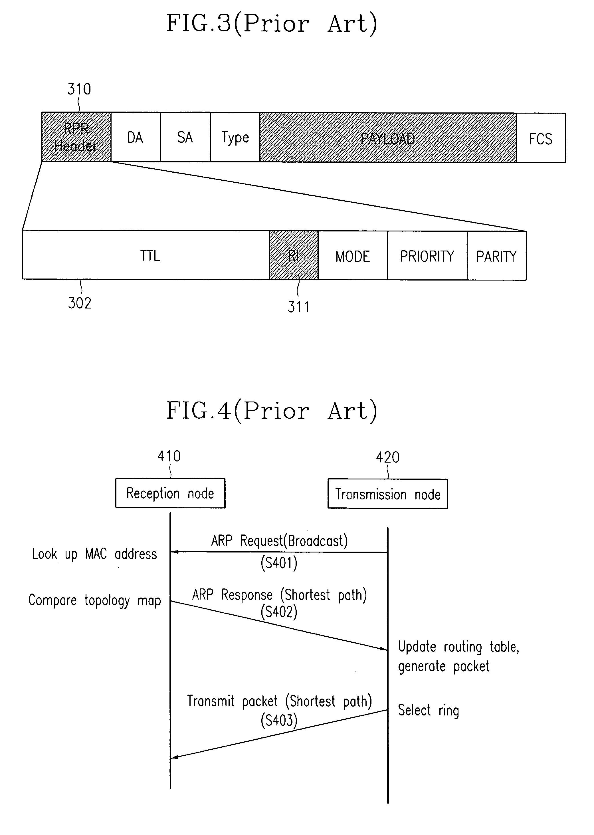
[0036] Preferably, in (a), all the nodes including transmission and reception nodes have a topology map through a topology packet change at the time od system initialization, the topology map including information on inter-node hop numbers, port information, MAC address, and wrapped-or-not information.
[0037] Preferably, the ring selection algorithm of (c) includes: the transmission node calculating a transmission coefficient using the hop number and delay time based on a path between the reception nodes, and the inter-node usage rate, storing the calculated transmission coefficient in the routing table, and selecting a ring having a lower transmission coefficient stored in the routing table as the reference value.
[0038] Preferably, the comparison with the reference values in (c) includes: determining whether or not the selected ring and the ring selected by the ring selection algorithm are matched to the reference values.
[0039] Preferably, the transmission coefficient is determined with reference to the hop number between the transmission node and the reception node, the usage rate of each node, and the inter-node delay time.

Problems solved by technology

But the token ring system is problematic in that the node is allowed to access the system only upon receiving the token, and it must be in a stand-by mode until the token is given.
Like the token ring system, the FDDI employs the token facing method, causing a deterioration of data transmission efficiency.
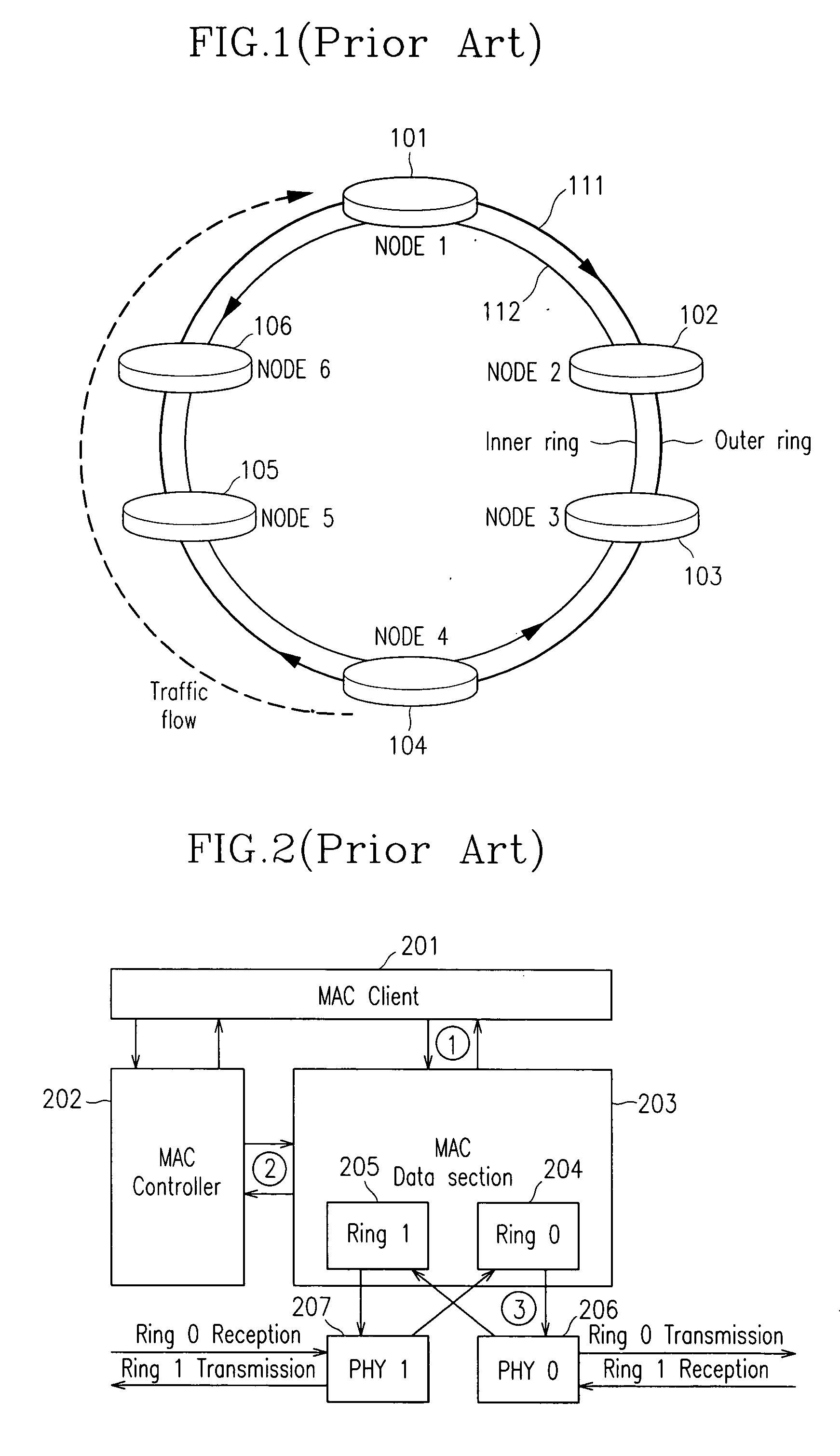
However, the above-stated method according to prior art solely considers the inter-node hop number in selecting a ring with reference to the routing table for selection of the RI of the packet header in generation of packets, thereby not making the best use of bandwidth, and it transmits an excessively large amount of packets impulsively on the same ring to cause congestion and hence a convergence of packets on the specific ring.

Method used


Image

  • Ring selection method for dual ring network
  • Ring selection method for dual ring network

Examples


Embodiment Construction

[0050] In the following detailed description, only the preferred embodiment of the invention has been shown and described, simply by way of illustration of the best mode contemplated by the inventor(s) of carrying out the invention. As will be realized, the invention is capable of modification in various obvious respects, all without departing from the invention. Accordingly, the drawings and description are to be regarded as illustrative in nature, and not restrictive.

[0051]FIG. 5 is a flow chart of a ring selection method for dual ring networks according to an embodiment of the present invention.

[0052] Referring to FIG. 5, every node connected to the dual ring network has a topology map through a topology packet change.

[0053] The topology map includes contents on inter-node hop numbers, port information, MAC address, and wrapped-or-not information.

[0054] Once all the nodes have the topology map, a transmission node 520 broadcasts an ARP request message to every node to get inf...


PUM


Abstract

A ring selection method for a dual ring network to perform node-to-node packet transmission. A transmission node transmits a reception node address request message for packet transmission to all nodes, and updates a routing table using information on a short path transferred from the reception node. The information on inter-node hop numbers included in the routing table is used to select a ring having the lowest hop number between the reception nodes It is then determined whether the selected ring is wrapped, and if the ring is not wrapped, comparing its usage rate and hop number to the reception node with reference values based on a ring selection algorithm; and if the ring is suitable based on the reference values, selecting the ring for packet transmission.

Description

BACKGROUND OF THE INVENTION [0001] (a) Field of the Invention [0002] The present invention relates to a ring selection method for dual ring networks. More specifically, the present invention relates to a ring selection method for dual ring networks that enables simultaneous data transmission of two rings in dual ring networks using a spatial reuse protocol. [0003] (b) Description of the Related Art [0004] There are different systems using a ring network structure, among which the token ring system is the earliest ring network. [0005] The token ring system is designed to transmit data only by a node with a received frame called a token. But the token ring system is problematic in that the node is allowed to access the system only upon receiving the token, and it must be in a stand-by mode until the token is given. [0006] Unlike the token ring system, FDDI (Fiber Distributed-Data Interface) employs a dual ring method. [0007] In FDDI, one ring is used for data transmission, and the oth...

Claims


Application Information

Patent Timeline
Patent Type & Authority Applications(United States)
IPC IPC(8): H04L12/42H04L12/46
CPCH04L12/4637H04L45/22H04L45/20H04L45/12H04L12/42
Inventor LEE, KANG-BOKLEE, HEYUNG-SUBLEE, HYEONG-HO
Owner ELECTRONICS & TELECOMM RES INST
Learn More