Measuring apparatus and measuring method

a technology of measuring apparatus and measuring method, which is applied in the direction of noise figure or signal-to-noise ratio measurement, instruments, transmission monitoring, etc., can solve the problems of preventing the high-precision measurement of the time it takes to measure the jitter transfer function, and the jitter tolerance measurement is one of the most difficult measurements

Active Publication Date: 2005-02-10
ADVANTEST CORP
View PDF21 Cites 61 Cited by
  • Summary
  • Abstract
  • Description
  • Claims
  • Application Information

AI Technical Summary

Benefits of technology

The jitter applying unit may supply the input signal to the electronic device, where the plurality of sinusoidal jitters having different frequency are applied to the input signal, and the jitter related transmission penalty estimator may estimate the reliability of the electronic device against jitter about every frequency of the sinusoidal jitter.

Problems solved by technology

Thus, it is apparent from the above that the jitter tolerance measurement is one of the most difficult measurements.
These phase noises prevent the high-precision measurement of the jitter transfer function.
Thus, it takes much time to measure the jitter transfer function.
Therefore; it is difficult to measure the fluctuation of the period between adjacent edges in the waveform of the input data or the output data.
Therefore, the jitter analyzer cannot precisely measure the instantaneous phases of the input data and the output data, so that it is difficult to precisely measure the jitter transfer function.
Therefore, it is found that the eye diagram cannot be applied to the jitter tolerance measurement.
However, since the output recovered clock is extracted from the serial bit stream in which edges fluctuate, it becomes difficult to sample the output recovered data at the optimum sampling instants under the condition of the large amplitude of the applied jitter.
In other words, in the jitter tolerance measurement using the bit error rate tester, it is likely to underestimate the jitter tolerance.
Timing degradation of the input bit stream as well as amplitude degradation increases the bit error rate.
From such a histogram, it is difficult to obtain ΔT.
Therefore, it is hard to reduce the measurement time.
Moreover, K in the above equation does not have an ideal value.
Therefore, the conventional apparatus is poor in efficiency, requiring the longer test time.

Method used


Image

  • Measuring apparatus and measuring method
  • Measuring apparatus and measuring method
  • Measuring apparatus and measuring method

Examples


Embodiment Construction

The invention will now be described based on the preferred embodiments, which do not intend to limit the scope of the present invention, but exemplify the invention. All of the features and the combinations thereof described in the embodiment are not necessarily essential to the invention.

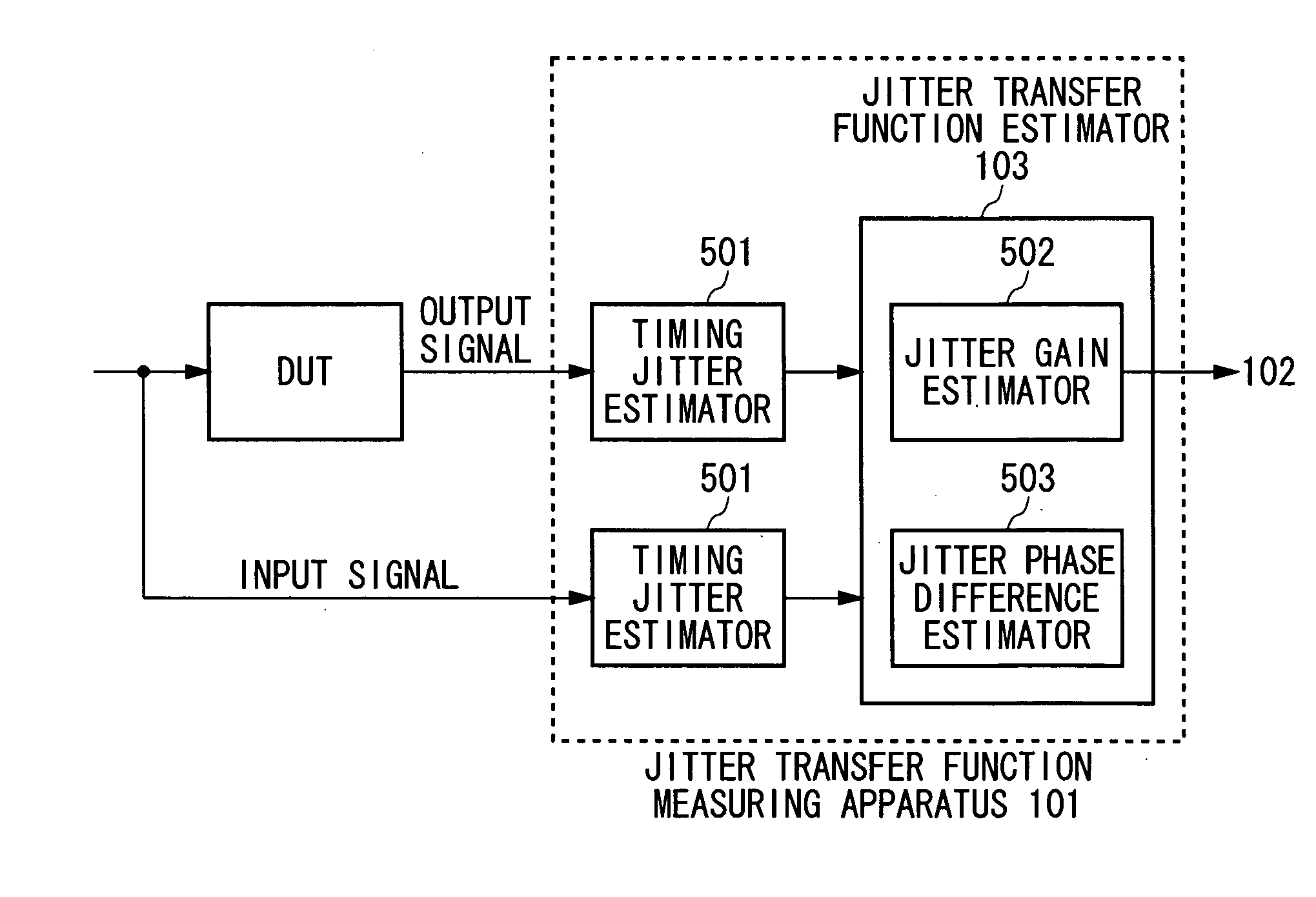
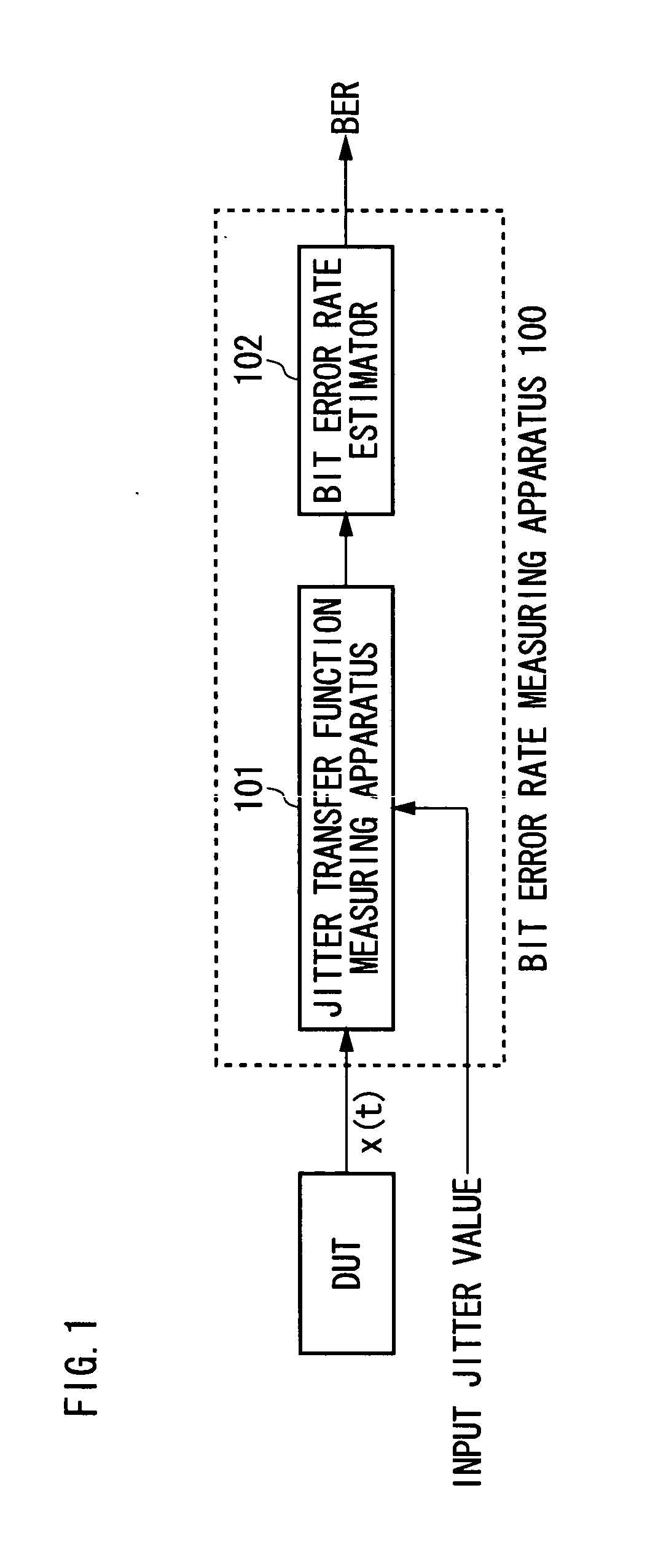
FIG. 1 illustrates an exemplary structure of a measuring apparatus 100 according to the present invention. The measuring apparatus 100 calculates a bit error rate of a circuit, electronic device or system under test (hereinafter, simply referred to as DUT). The measuring apparatus 100 includes a jitter transfer function measuring apparatus 101 operable to measure jitter transfer function of the DUT, and a bit error rate estimator 102 operable to estimate the bit error rate of the DUT based on the jitter transfer function measured by the jitter transfer function measuring apparatus 101. The bit error rate estimator 102 estimates the bit error rate of the DUT based on the gain of the jitter transfe...


PUM


Abstract

A measuring apparatus including a timing jitter estimator which estimates an output timing jitter sequence which indicates the output timing jitter of an output signal based on an output signal output from a DUT in response to an input signal input to the DUT, and a jitter transfer function estimator which estimates a jitter transfer function in the DUT based on the output timing jitter sequence. The jitter transfer function estimator includes an instantaneous phase noise estimator which estimates an instant phase noise of the output signal based on an output signal, and a resampler which generates the output timing jitter sequence by resampling the instantaneous phase noise at predetermined timing.

Description

BACKGROUND OF THE INVENTION 1. Field of the Invention The present invention relates to a measuring apparatus and a measuring method for measuring an electronic device. More particularly, the present invention relates to a measuring apparatus and a measuring method that measure a jitter transfer function, a bit error rate and jitter tolerance of the electronic device under test. 2. Related Art Jitter testing is an important item to a serial-deserial communication device. For example, Recommendations and Requirements from International Telecommunication Union and Bellcore ((1) ITU-T, Recommendation G.958: Digital Line Systems Based on the Synchronous Digital Hierarchy for Use on Optical Fibre Cables, November 1994, (2) ITU-T, Recommendation O.172: Jitter and Wander Measuring Equipment for Digital Systems Which are Based on the Synchronous Digital Hierarchy (SDH), March 1999, (3) Bellcore, Generic Requirements GR-1377-Core: SONET OC-192 Transport System Genetic Criteria, December 1...

Claims


Application Information

Patent Timeline
Patent Type & Authority Applications(United States)
IPC IPC(8): G01R29/26G01R31/317G01R31/319G01R31/3193H04L1/20
CPCG01R29/26G01R31/31709G01R31/3171H04L1/205G01R31/31922G01R31/31937G01R31/31725
Inventor YAMAGUCHI, TAKAHIROISHIDA, MASAHIROSOMA, MANIMUSHA, HIROBUMI
Owner ADVANTEST CORP
Why Eureka
Try Eureka