Thermal joint and bone compression system

a technology of bone compression and joint, applied in the field of thermal joint and bone compression system, can solve the problems of not meeting the needs of maximizing compression, lack of design in several areas of improvement, and device not covering the areas needed to cover efficiently, etc., and achieve the effect of quick and easy connection

Inactive Publication Date: 2005-02-10
MCCONNELL DEAN EDWARD
View PDF3 Cites 46 Cited by
  • Summary
  • Abstract
  • Description
  • Claims
  • Application Information

AI Technical Summary

Benefits of technology

[0011] A thermal compression system is disclosed that includes an electric fluid pump that is used to transfer fluid from a fluid container to a cuff that is attached to a portion of the body that is being treated. The fluid container includes a fluid output line and a fluid input line. The fluid output li

Problems solved by technology

This approach is simple and economical, but it has complications.
It has been demonstrated that an ace wrap applied to the knee at a moderate compression retard venous circulation and may contribute to thromboembolism.
None of these systems or any other known system have addressed the need for maximizing the compression and cold in areas where needed, while minimizing compression in those areas most sensitive to restriction of venous circulation.
While the device disclosed in the Johnson, Jr. et al. patent addresses some of the issues that need to be addressed in thermal compression devices, its design is lacking in several areas in which improvements

Method used


Image

  • Thermal joint and bone compression system
  • Thermal joint and bone compression system
  • Thermal joint and bone compression system

Examples


Embodiment Construction

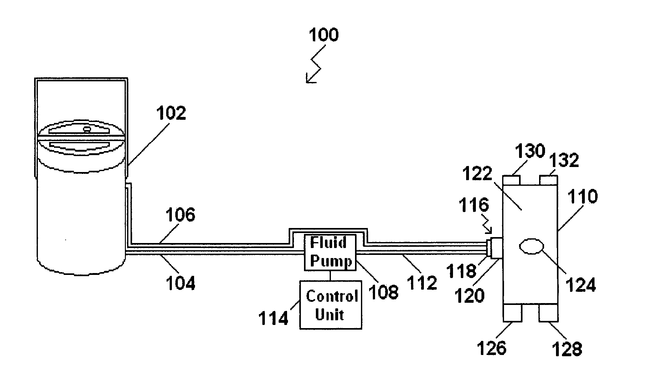
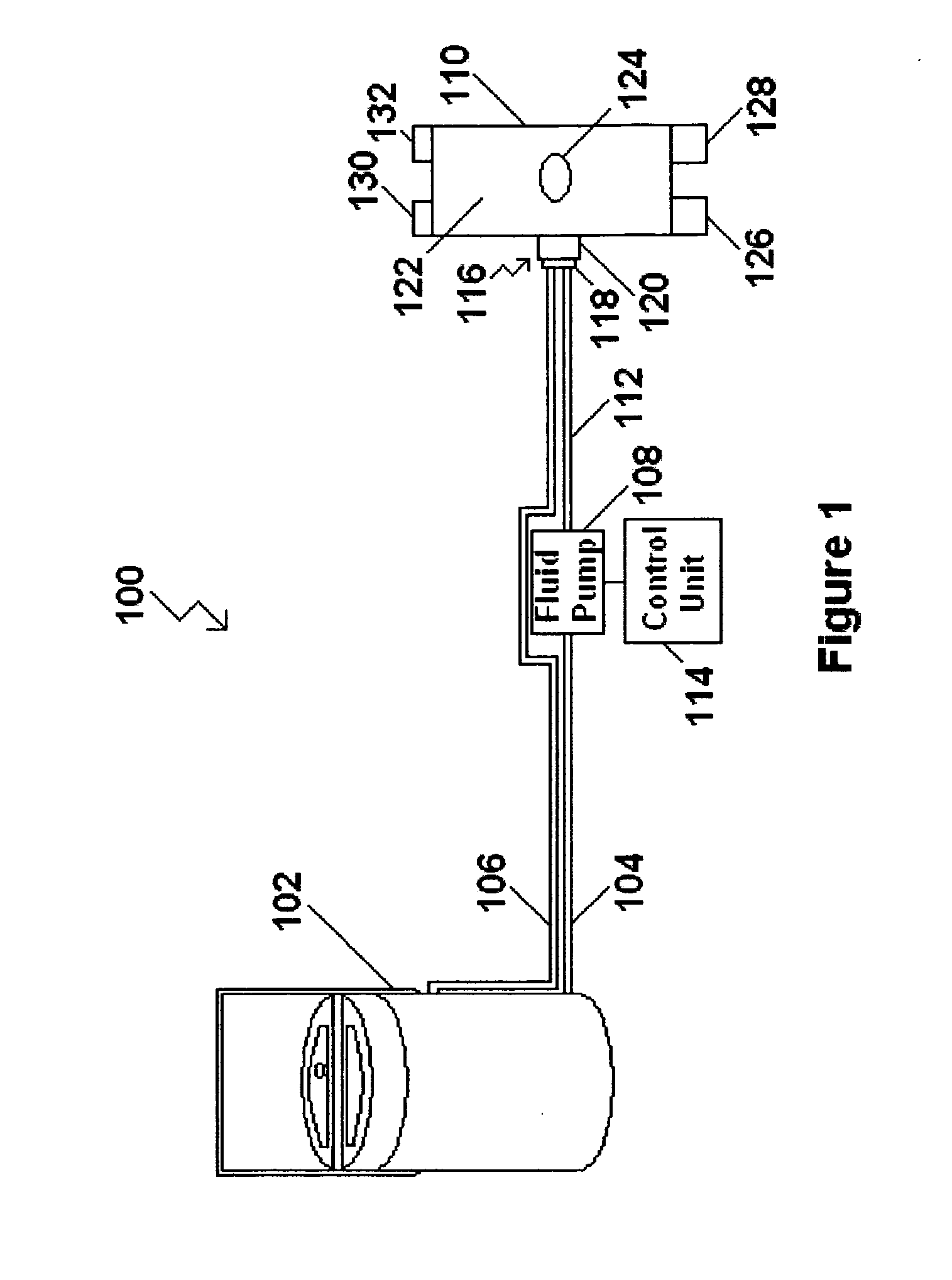
[0026] Referring to FIG. 1, a thermal compression system 100 is illustrated that is used to apply hot or cold fluid in combination with compression to a portion of a limb of a human body or an animal body. While the thermal compression system 100 disclosed herein may be used with hot or cold fluid, a majority of the description set forth below will focus on the use of cold fluid where its greatest use is anticipated. The thermal compression system 100 illustrated in FIG. 1 is formed to treat a knee of an individual. However, it should also be recognized that other areas of the body may be treated using one of several thermal compression systems 100 that may be formed in various different shapes designed to accommodate different areas of the human body.

[0027] The thermal compression system 100 may include a fluid container 102 that may be used to hold cold or hot fluid. In the case of cold fluid, the fluid container 102 may be filled with ice and water or any other suitable fluid th...


PUM


Abstract

A thermal compression system adapted to encompass a knee or any other portion of a limb is disclosed. The thermal compression system includes a container that has a fluid output line and a fluid input line. A fluid pump is connected with the fluid output line of the container and a fluid input of a cuff. The cuff is designed to be attached to an area of the body being treated. The pump fills the cuff with fluid and the fluid may exit the cuff through a fluid output of the cuff that is connected with the fluid input line of the container.

Description

FIELD OF THE INVENTION [0001] The present invention relates generally to systems and methods used in the application of fluid in combination with compression to certain injured portions of the human body and more particularly, to a system and method for therapeutically applying fluid in combination with compression to a portion of a limb and replacing the fluid in the cuff applied to the limb. BACKGROUND OF THE INVENTION [0002] The therapeutic value of simultaneous application of cold and compression to an injured body part is widely accepted in the medical community, and the acronym RICE for Rest, Ice, Compression, and Elevation, for the primary treatment of injury to joints and limbs of the body, is practiced routinely. For example, after knee surgery, compression and cold are almost universally applied to control the swelling and the commonly occurring hemarthrosis that causes pain and delays rehabilitation [0003] Methods used for postoperative cold and compression traditionally ...

Claims


Application Information

Patent Timeline
IPC IPC(8): A61F7/00A61F7/02
CPCA61F7/02A61F2007/0054A61F2007/0001
Inventor MCCONNELL, DEAN EDWARD
Owner MCCONNELL DEAN EDWARD
Why Eureka
Try Eureka