Scheduling technique for software pipelining

a software and schedule technology, applied in the field of computer systems and programs, can solve the problems of cumbersome bunching of instructions at various times, inability to find optimal schedules, and difficulty in finding optimal schedules

Inactive Publication Date: 2005-02-10
IBM CORP
View PDF4 Cites 13 Cited by
  • Summary
  • Abstract
  • Description
  • Claims
  • Application Information

AI Technical Summary

Problems solved by technology

In certain situations, SMS and other known software pipelining techniques may fail to find an optimal schedule.
In particular, finding the optimal schedule may be difficult when there are multiple groups of instructions (i.e. sub-graphs) which are independent, and substantially identical in structure (for example, this may result from “unrolling” a loop of a computer program where th

Method used


Image

  • Scheduling technique for software pipelining
  • Scheduling technique for software pipelining
  • Scheduling technique for software pipelining

Examples


example

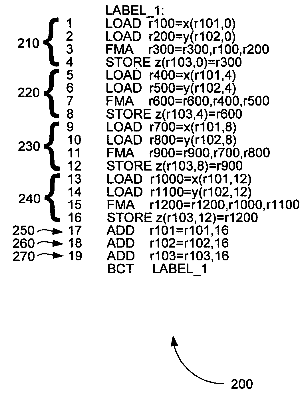
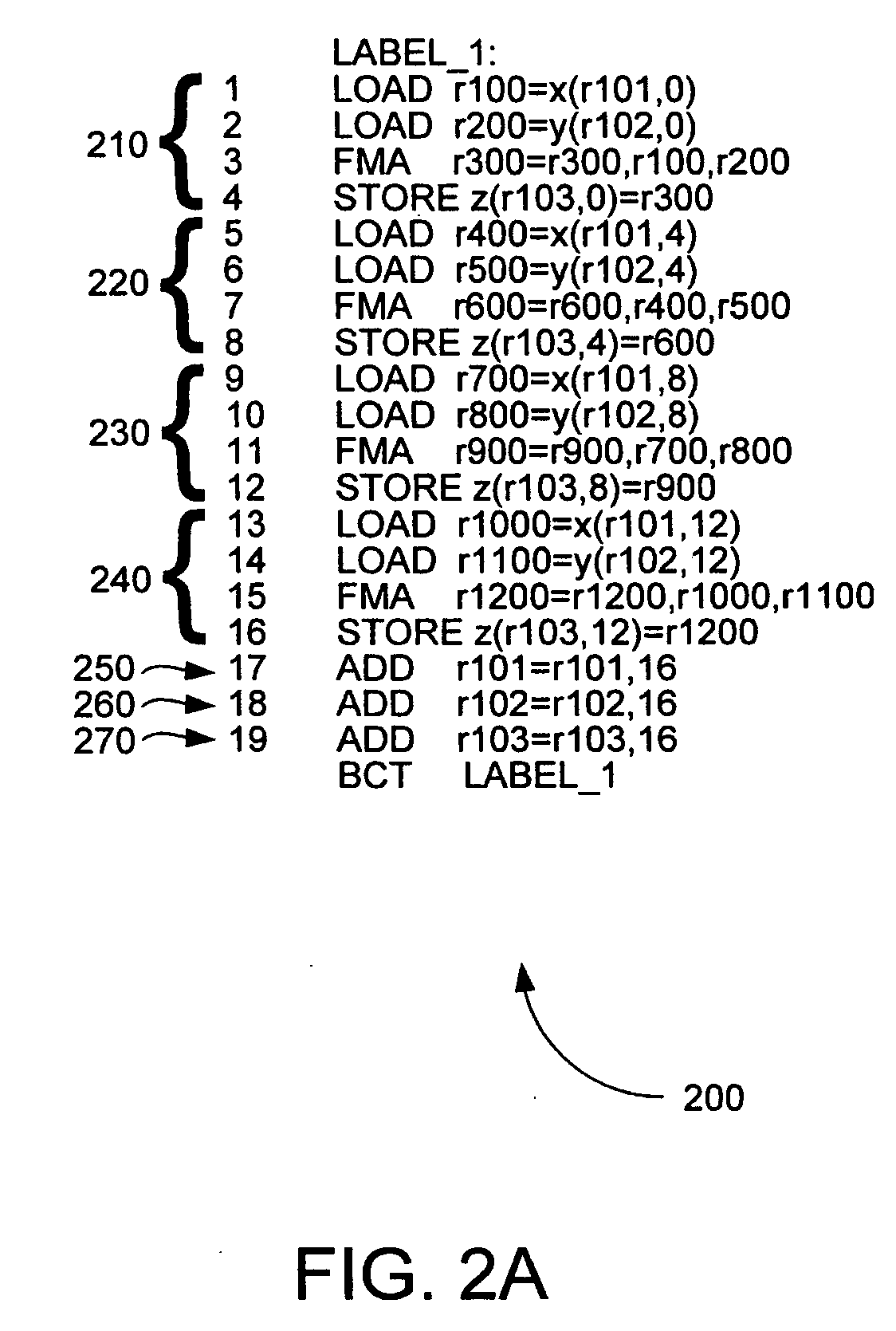
Consider the illustrative scheduling process 400A in FIG. 4A. By way of example, this scheduling process 400A may be generated by using the SMS technique introduced above to schedule the looped computer program 200 of FIG. 2. As shown, the scheduling process 400A may comprise a plurality of “scheduler actions”, labeled by reference numerals 401-415. Corresponding actual (i.e. physical) “machine usage” is shown to the right of each “scheduler action”401-415.

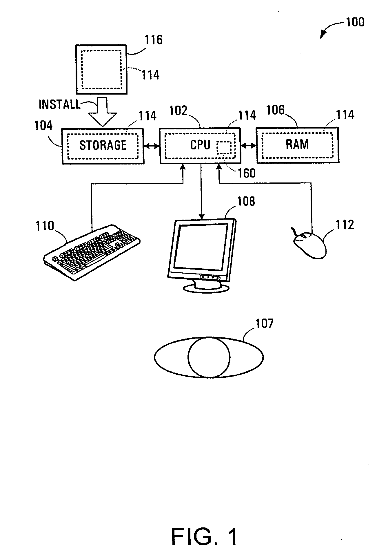
More specifically, “machine usage” may be explained as follows. Consider a microprocessor having different resources available for use in each clock cycle. Typical types of resources available may include, for example, “issue” units, “arithmetic execution” units, and “load / store” units. If a loop contains certain instructions, then the number of resources required for executing the loop can be calculated. Then, for each resource available, the minimum execution time of the loop can be calculated by: min_time=(resources required...


PUM


Abstract

An improved scheduling technique for software pipelining is disclosed which is designed to find schedules requiring fewer processor clock cycles and reduce register pressure hot spots when scheduling multiple groups of instructions (e.g. as represented by multiple sub-graphs of a DDG) which are independent, and substantially identical. The improvement in instruction scheduling and reduction of hot spots is achieved by evenly distributing such groups of instructions around the schedule for a given loop.

Description

BACKGROUND The present invention relates generally to computer systems and programs, and more specifically to an improved scheduling technique for software pipelining. Software pipelining is a compiler optimization technique for reordering hardware instructions within a given loop of a computer program being compiled, so as to minimize the number of cycles required to execute each iteration of the loop. More specifically, software pipelining attempts to optimize the scheduling of such hardware instructions by overlapping the execution of instructions from multiple iterations of the loop. For the purposes of the present discussion, it may be helpful to introduce some commonly used terms in software pipelining. As well known in the art, individual machine instructions in a computer program may be represented as “nodes” having assigned node numbers, and the dependencies and latencies between the various instructions may be represented as “edges” between nodes in a data dependency gr...

Claims


Application Information

Patent Timeline
IPC IPC(8): G06F9/45
CPCG06F9/3838G06F8/4452
Inventor MARTIN, ALLAN RUSSELLMCINNES, JAMES LAWRENCE
Owner IBM CORP
Why Eureka
Try Eureka