Structure and method to compensate for thermal edge loss in thin film heaters

a thin film heater and thermal edge loss technology, applied in the field of thin film heaters, can solve the problems of thermal uniformity that can involve some trial and error, and the attainment of various areas of thin film material can vary widely, so as to improve overall temperature uniformity, good thermal uniformity, good thermal uniformity

Active Publication Date: 2005-02-17
THERMO STONE USA
View PDF26 Cites 14 Cited by
  • Summary
  • Abstract
  • Description
  • Claims
  • Application Information

AI Technical Summary

Benefits of technology

[0021] The present invention compensates at least in part for edge loss effects in thin film heaters, including loss due to heat sinks, by removing preferably elongated regions of the thin film material adjacent substrate edges parallel to regions where the connective buss bar structures are formed. After these preferably elongated regions are defined, underlying substrate material becomes exposed. Alternately, during deposition of thin film material over the substrate, masking or other techniques can be used to prevent deposition over the desired elongated regions.
[0022] The removal of such regions of material from the otherwise continuous thin film material appears to control current densities within the resistive thin film material that enhances overall temperature uniformity. Arriving at a configuration or pattern of regions to be removed from the thin film material to yield acceptably good thermal uniformity can involve some trial and error. However once the configuration pattern has been determined, thin film heaters can then be mass produced using the pattern with consistently good thermal uniformity.

Problems solved by technology

Unfortunately the temperature attained at various areas on the thin film material can vary widely from an intended thermal set point, due in part to so-called edge loss effects at the perimeter of the heater.
Arriving at a configuration or pattern of regions to be removed from the thin film material to yield acceptably good thermal uniformity can involve some trial and error.

Method used


Image

  • Structure and method to compensate for thermal edge loss in thin film heaters
  • Structure and method to compensate for thermal edge loss in thin film heaters
  • Structure and method to compensate for thermal edge loss in thin film heaters

Examples


Embodiment Construction

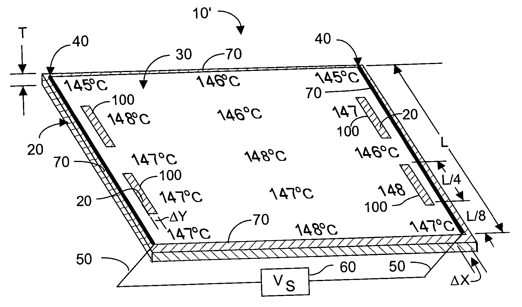
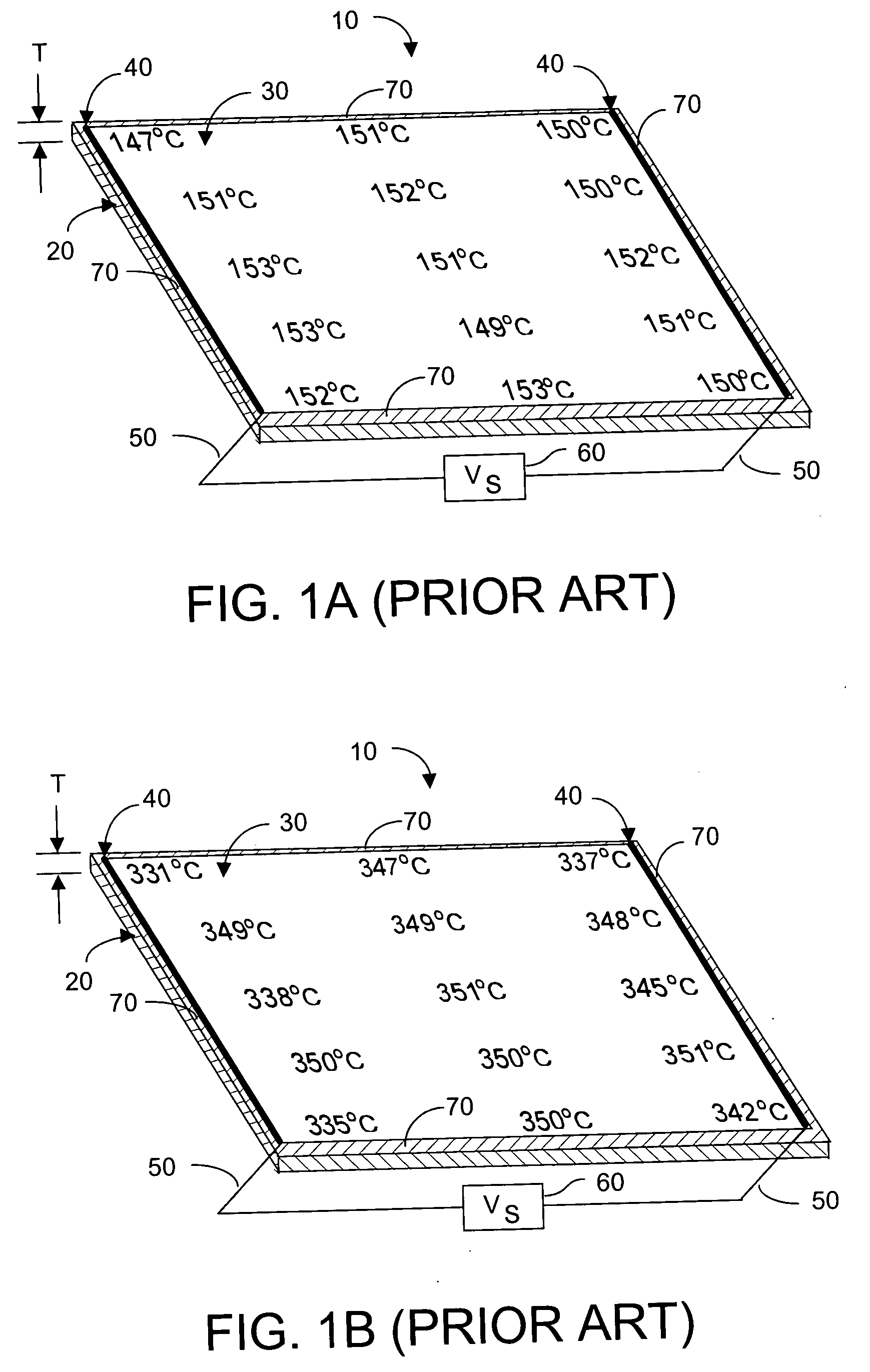
[0040]FIG. 2A depicts a thin film heater 10′ according to the present invention. Thin film heater 10′ is fabricated upon a surface of substrate 20 that may be identical in material composition to prior art thin film heaters such as have been described herein with respect to FIGS. 1A-1G. A layer of electrically conductive thin film material 30 is formed or deposited atop substrate 20, and the type of material used for thin film 30 may be identical to materials such as have been described herein. Substrate 20 will have an upper and a lower surface, and for ease of description it will be assumed that the thin film material will be formed or deposited on the upper substrate surface. Typically the substrate will have at least two edges that are spaced-apart and are substantially parallel to each other. In FIG. 2A, substrate 20 is rectangular in shape, and thus has two pairs of edges that are spaced-apart and are substantially parallel to each other.

[0041] However during deposition or fo...


PUM

PropertyMeasurementUnit
temperatureaaaaaaaaaa
voltage Vsaaaaaaaaaa
temperaturesaaaaaaaaaa

Abstract

A thin film heater includes at least two open regions formed along each of two spaced-apart edges of the thin film material, which edges are parallel to two spaced-apart edges of the underlying substrate. The open regions expose areas of underlying substrate. When electrical power is coupled to the two spaced-apart edges of the thin film material, uniformity of the heat generated across the thin film material is enhanced. The substrate may be planar or curved, and the open regions in the thin film material may be removed from deposited thin film material, or may be formed by preventing deposition of thin film material in such regions.

Description

FIELD OF THE INVENTION [0001] The present invention relates generally to thin film heaters, and more particularly to providing thermal heaters with improved thermal uniformity by compensating for thermal edge loss and effects of heat sinks. BACKGROUND OF THE INVENTION [0002] Thin film heaters typically comprise a growth or deposition of a thin film of electrically conductive resistive material on an electrically insulating support substrate, e.g., glass, quartz, glass ceramic, alumina, etc. Alternatively, the thin film material can be deposited upon a substrate that is electrically conductive, e.g., stainless steel, if the deposition surface of the substrate is first treated with a dielectric coating, e.g., DuPont™ material part number 3500, or Electro Science Laboratories material, part number 4914. Other dielectric coating materials may be used, if desired. [0003] In a thin film heater, when a source of voltage is coupled across the thin film resistive material, the resultant elec...

Claims


Application Information

Patent Timeline
Patent Type & Authority Applications(United States)
IPC IPC(8): H01C17/075H05B3/26
CPCH01C17/075H05B3/262Y10T29/49083H05B2203/013H05B2203/017H05B3/265
Inventor GOODSEL, ARTHUR J.COOPER, SCOTT A.GOODSEL, KERRY A.
Owner THERMO STONE USA
Why Eureka
Try Eureka