
Charged particle deflecting system

a deflecting system and charged particle technology, applied in magnetic discharge control, instruments, nuclear engineering, etc., can solve the problems of introducing astigmatism to the charged particle beam, and affecting the achievable spatial resolution, so as to reduce interference of the primary charged particle beam and simplify the beam optics

Active Publication Date: 2005-02-17
ICT INTEGRATED CIRCUIT TESTING GESELLSCHAFT FUER HALBLEITERPRUEFTECHNIK GMBH
View PDF14 Cites 20 Cited by
  • Summary
  • Abstract
  • Description
  • Claims
  • Application Information

AI Technical Summary

Benefits of technology

[0014] In particular, the present invention is intended to provide a deflecting system which keeps the astigmatism of the charged particle beam low despite the at least two deflections. A low astigmatism helps to reduce the beam spot size of the charged particle beam and, therefore, improves the spatial resolution of a probing or structuring charged particle beam device.
[0033] Preferably, the charged particle beam device includes a high voltage beam tube surrounding the charged particle beam to protect the charged particle beam from external electric fields on its way from the charged particle beam source to a specimen. The high voltage beam tube is also known as “liner tube”. Preferably, the liner tube is at a high voltage with respect to the specimen and / or with respect to the charged particle beam source (say more than 1000 V) in order to accelerate the charged particles beam and / or the secondary charged particles coming from the specimen to a high voltage. With the secondary charged particles and the primary charged particles directed in opposite directions, the two can be spatially separated by the deflecting system according to the invention without using additional beam optical components. This greatly simplifies the beam optics and reduces the interference of the primary charged particle beam by beam optical components used for the guidance of the secondary charged particles to the detector.

Problems solved by technology

Unfortunately, deflections of charged particle beams are known to introduce an astigmatism to a charged particle beam.
Astigmatism is problematic for a high spatial resolution operation, since the probing area of an astigmatic deformed beam is larger than the probing area of the previously circular cross section of the beam.
This worsens the achievable spatial resolution.
Even worse, astigmatism may accumulate with each deflection which for a beam optical design limits the number of deflections as well as the maximum deflection angles to meet given spatial resolution requirements.
Astigmatism, therefore, is a severe problem for charged particle beam devices where the primary charged particle beam is experiencing several deflections in a row, such as, for example, in a scanning electron microscope (SEM) where magnetic deflectors are used as separators to separate the primary charged particle beam from the beam of secondary charged particles generated by the primary charged particle beam on the specimen.
However, the more deflecting stages the deflection system has, the larger the astigmatism accumulated over the various deflection stages.
Astigmatism becomes even more a problem when a charged particle beam device comprises a two-dimensional deflecting system consisting of two deflecting systems which deflect the charged particle beam within two different deflection planes, e.g. within the orthogonal X-plane and Y-planes.

Method used


Image

  • Charged particle deflecting system
  • Charged particle deflecting system
  • Charged particle deflecting system

Examples


Embodiment Construction

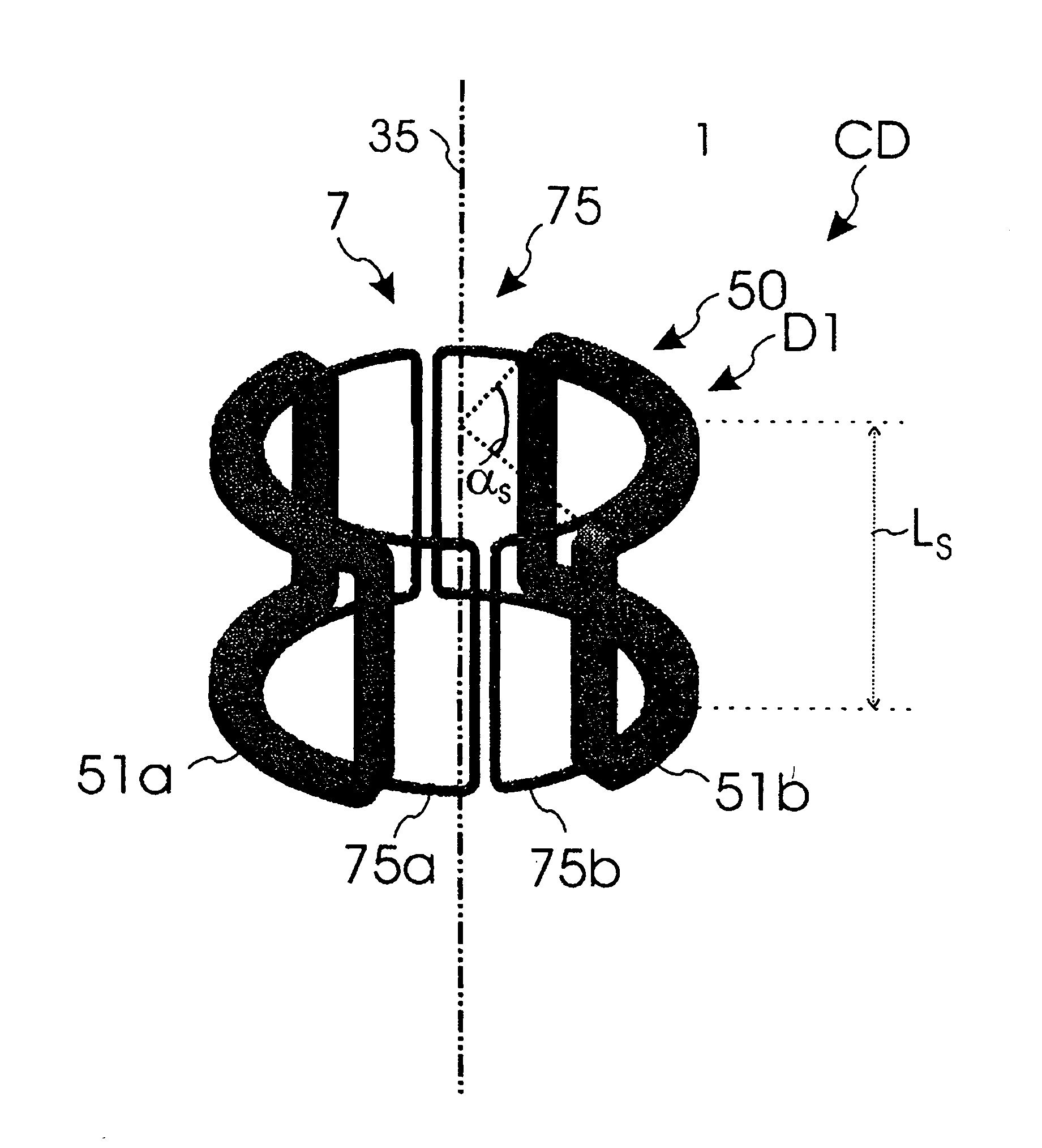
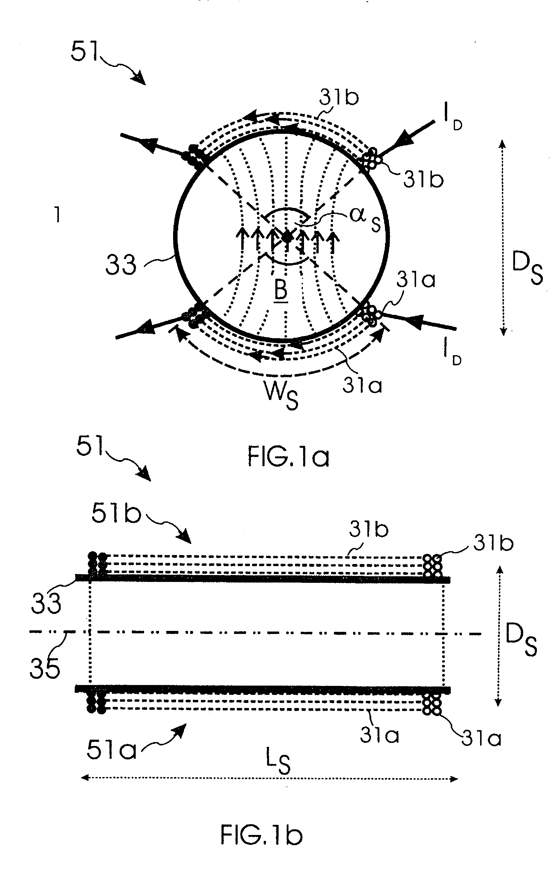
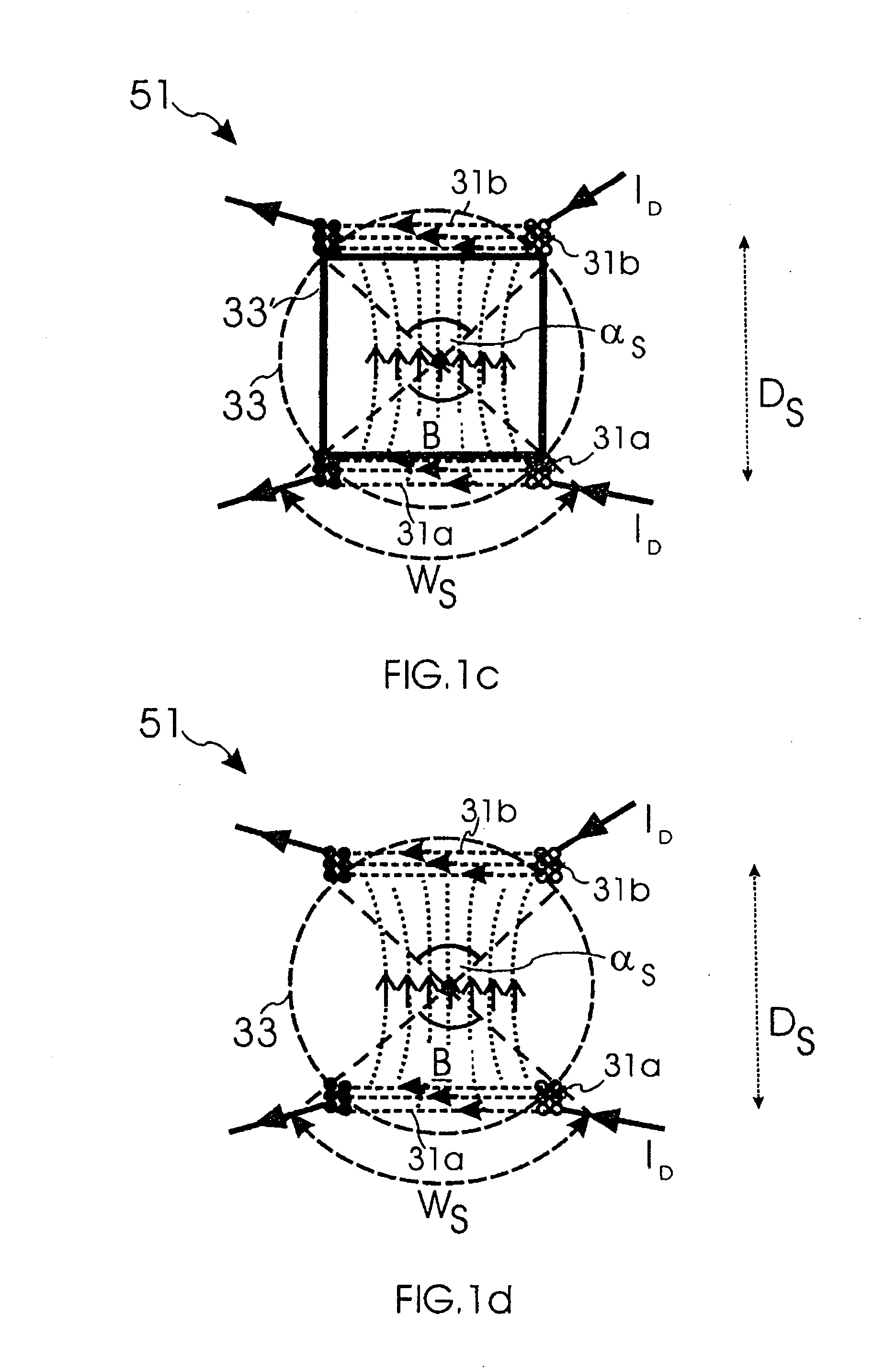
[0059] The deflecting system 1 according to one embodiment of the invention includes at least two of the deflectors D1, D2, D3, D4. The deflectors can the any device which is capable of changing the direction of the charged particle beam 3. Preferably, the deflectors D1, D2; D3 and D4 are either electric deflectors, magnetic deflectors or a combination of the two. If a deflector D1, D2, D3, D4 is an electric deflector, the deflector usually comprises a pair of electrodes with the two electrodes having two different voltages to generate a deflecting electric dipole field between the two electrodes. If a deflector D1, D2, D3, D4 is a magnetic deflector, the deflector usually comprises a pair of deflecting coils 50 which is provided with a deflecting current I˜ to generate a deflecting magnetic dipole field between the two coils. For the sake of simplicity, the description below will concentrate on magnetic deflectors without limiting the scope of the invention.

[0060] If a deflector D...


PUM


Abstract

The invention provides a deflecting system for deflecting a charged particle beam from a first direction to a second direction, the deflecting system comprising a first deflector for deflecting said charged particle beam off the first direction within a first deflection plane; a second deflector for deflecting the deflected charged particle beam into the second direction within the first deflection plane; and at least one deflect pair of correcting coils comprising two correction coils which are positioned and shaped t reduce an astigmatism of the charged particle beam caused by the deflections.

Description

CROSS-REFERENCE TO RELATED APPLICATIONS [0001] This application claims foreign priority benefits under 35 U.S.C. §119 to co-pending European patent application number 03013848.1, filed Jun. 18, 2003. This related patent application is herein incorporated by reference in its entirety.BACKGROUND OF THE INVENTION [0002] 1. Field of the Invention [0003] The invention relates to a deflecting system for deflecting a charged particle beam whereby the deflecting system comprises at least two deflectors. The invention further relates to a charged particle beam device comprising a deflecting system to separate the charged particle beam from secondary charged particles. [0004] 2. Description of the Related Art [0005] Charged particle beam devices like electron beam microscopes or electron beam pattern generators use charged particle beams to probe or structure a specimen with high spatial resolution. For the high spatial resolution, the charged particle beam has to be directed and focused with...

Claims


Application Information

Patent Timeline
IPC IPC(8): H01J37/147H01J37/153H01J37/256H01J37/28
CPCH01J37/1475H01J37/153H01J2237/1536H01J2237/1532H01J2237/141
Inventor ADAMEC, PAVELMUNACK, HARRY
Owner ICT INTEGRATED CIRCUIT TESTING GESELLSCHAFT FUER HALBLEITERPRUEFTECHNIK GMBH
Learn More