Range finder and method
- Summary
- Abstract
- Description
- Claims
- Application Information
AI Technical Summary
Benefits of technology
Problems solved by technology
Method used
Image
Examples
embodiment 1
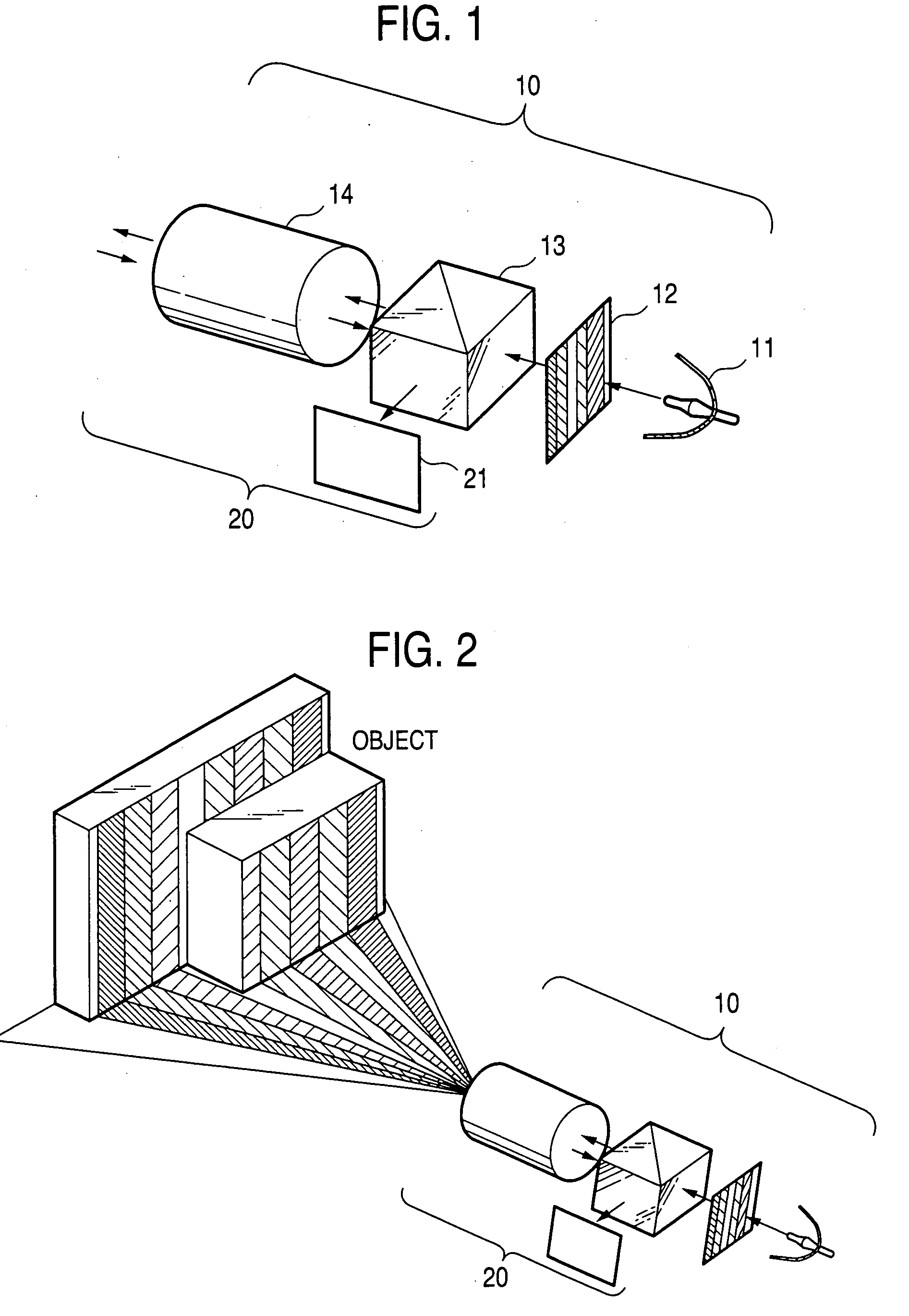
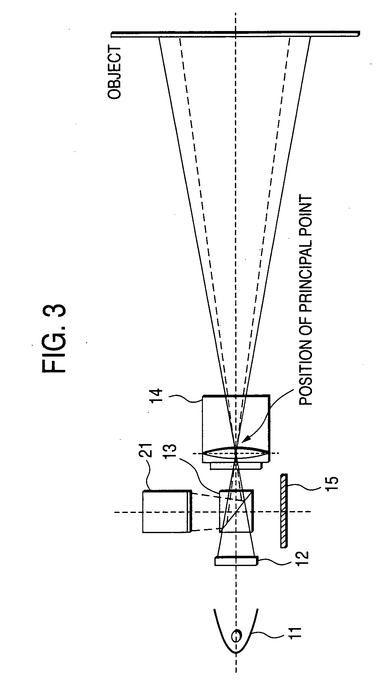
[0047]FIG. 1 schematically shows projector unit 10 which is the principal feature of a range finder of the invention; and first image capturing unit 20 located at a principal point optically identical with that of the projector unit 10. The schematic configuration of the entirety of the range finder of the present embodiment is shown in FIG. 4, and the configuration will be described later.
[0048] In FIG. 1, the projector unit 10 comprises a light source 11 for emitting light; a pattern generation section 12 for generating an encoded pattern; identical principal point arrangement unit 13 for placing the projector unit 10 at the principal point optically identical with that of first image capturing unit 20; and an image forming optical system 14 shared between the projector unit 10 and the first image capturing unit 20. A liquid-crystal panel or a transmitted film is used for the pattern generation section 12. If a liquid-crystal panel is used, the contrast or color of stripes consti...
sixth embodiment
[0089] A sixth embodiment will now be described. The previously-described Embodiments 1 through 5 have used a polarized beam splitter as the identical principal point arrangement unit and have utilized a polarization light converting function and a polarization light direction selection function, both belonging to the beam splitter. However, when the gloss of the object does not present any significant problem or when means for solving a problem related to a gloss is additionally adopted, the polarization light converting function and the polarization light direction selection function can be omitted. Subsequent embodiments employ identical principal point arrangement unit which does not have any polarization light converting function or polarization light direction selection function.
embodiment 6
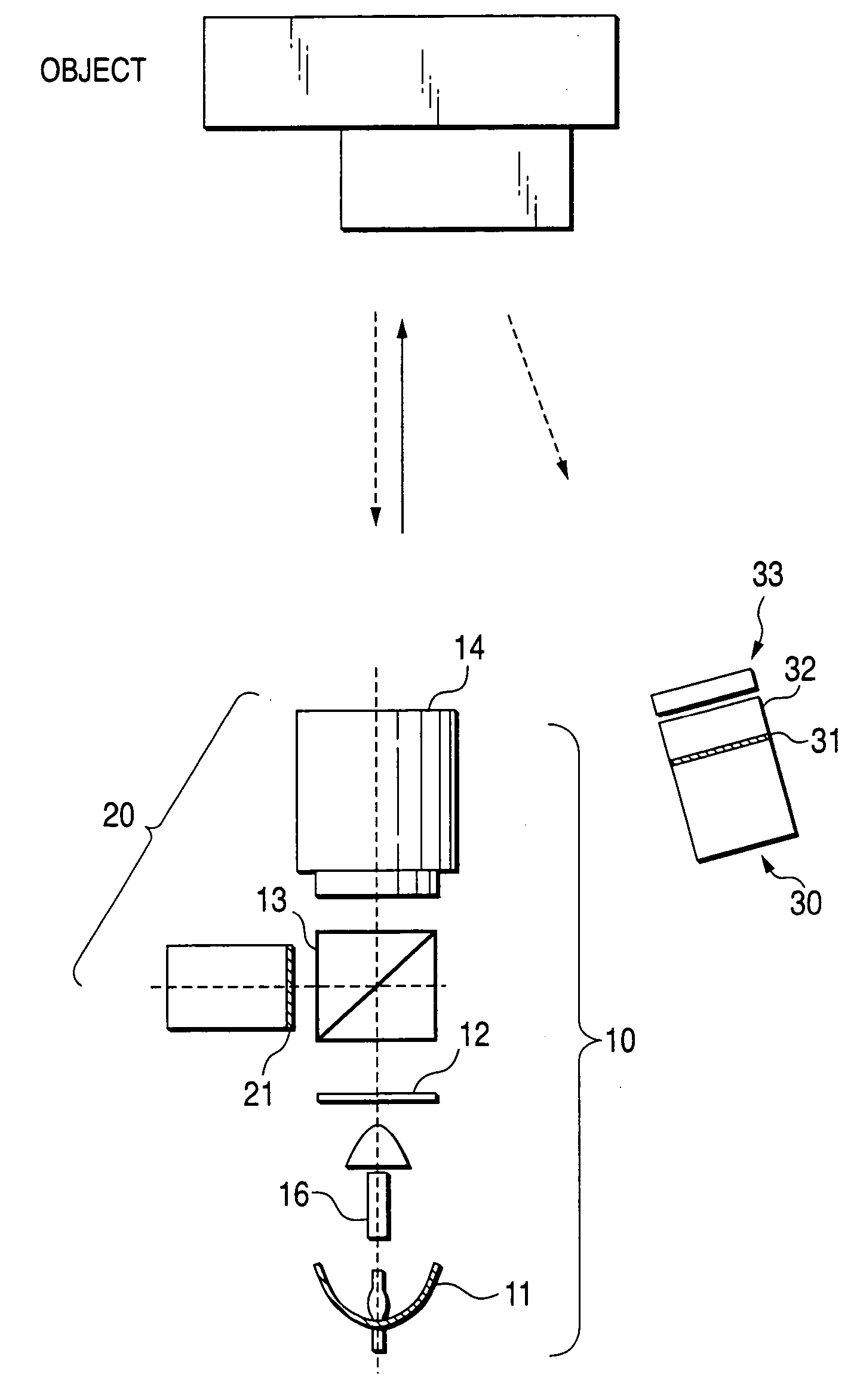
[0090]FIG. 14 shows a range finder of In the drawing, elements which correspond to those shown in FIG. 4 are assigned corresponding reference numerals. The present embodiment employs a beam splitter (of cube or plate type) as identical principal point arrangement unit 13A. Second image capturing unit 30A has the texture pattern image capturing section 31 and the imaging optical system 32. However, the image capturing unit 30A is not provided with the polarizing direction selection unit (indicated by reference numeral 33 in FIG. 4).
[0091] Even in the range finder of Embodiment 6, the stripe images captured by the first image capturing unit 20 and the second image capturing unit 30A include texture data pertaining to the object. Hence, when corresponding points are extracted through comparison between the stripe images, occurrence of an error can be inhibited. Therefore, the influence of measurement deterioration attributable to the texture of the object can be lessened.
[0092] When ...
PUM
 Abstract
Description
Claims
Application Information
 - R&D
- Intellectual Property
- Life Sciences
- Materials
- Tech Scout
- Unparalleled Data Quality
- Higher Quality Content
- 60% Fewer Hallucinations
Browse by: Latest US Patents, China's latest patents, Technical Efficacy Thesaurus, Application Domain, Technology Topic, Popular Technical Reports.
© 2025 PatSnap. All rights reserved.Legal|Privacy policy|Modern Slavery Act Transparency Statement|Sitemap|About US| Contact US: help@patsnap.com


