Linear actuator with an internal dampening mechanism

a technology of dampening mechanism and linear actuator, which is applied in the direction of bumpers, explosive based starters, tractor, etc., can solve the problems of unsuitable for many commercial applications, high production cost, and inability to meet the requirements of many commercial applications, so as to reduce the kinetic energy of the piston, dampen the movement of the piston, and increase the pressure behind the head portion

Inactive Publication Date: 2005-02-17
AUTOLIV ASP INC
View PDF11 Cites 38 Cited by
  • Summary
  • Abstract
  • Description
  • Claims
  • Application Information

AI Technical Summary

Benefits of technology

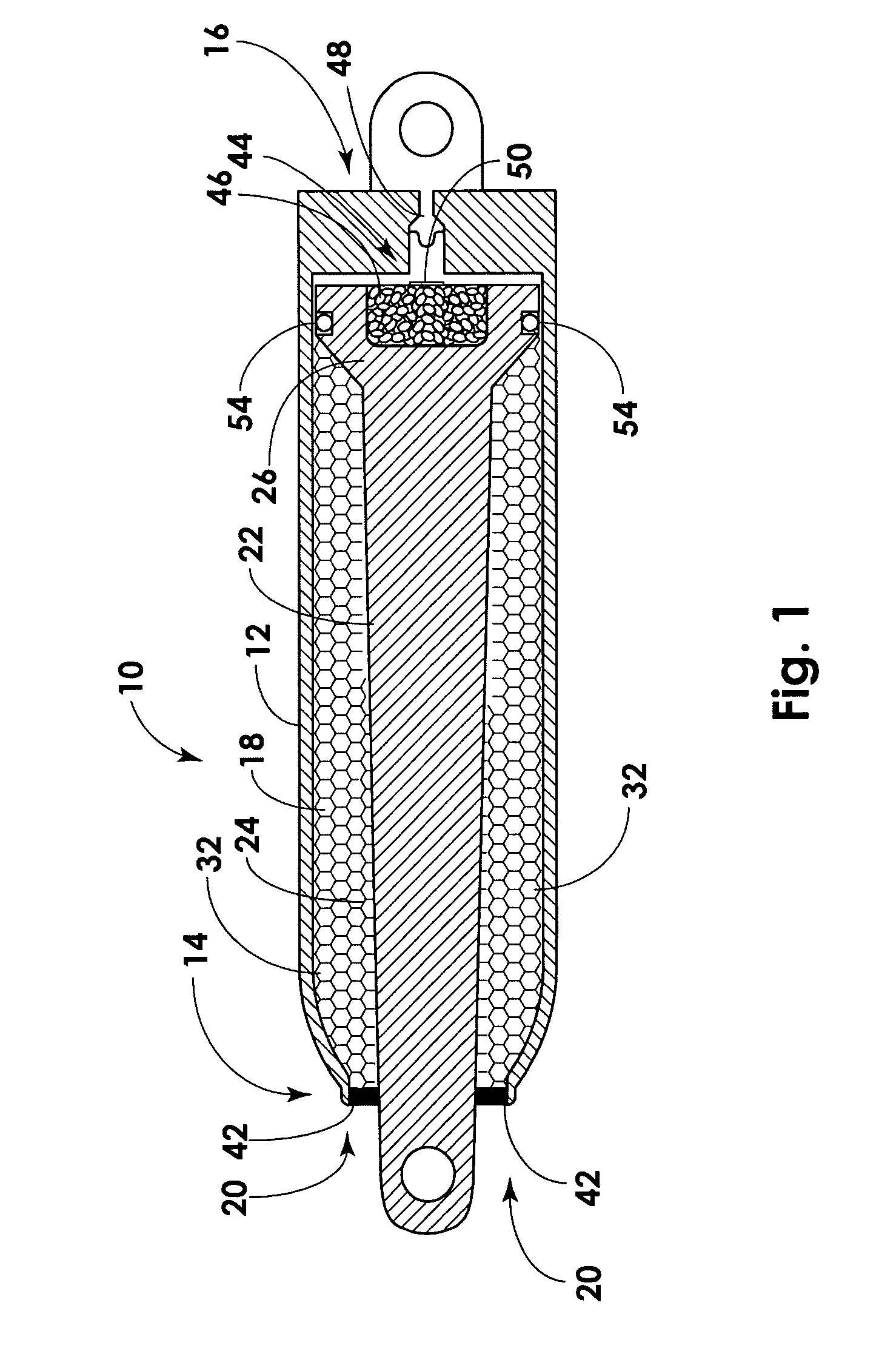
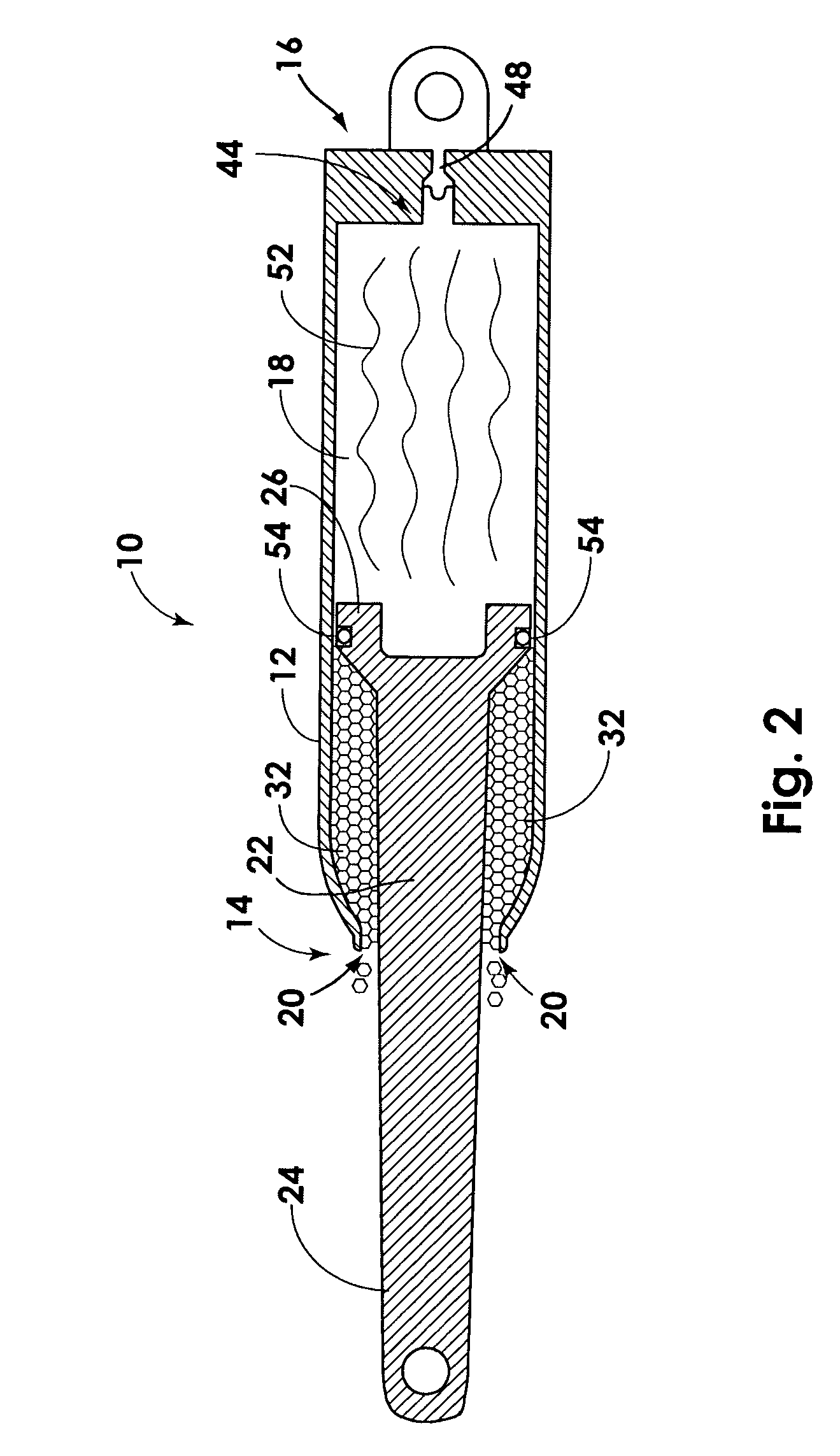
[0027] The displacement mechanism is capable of causing the actuator to undergo the deployment process. The “deployment process” is the process by which the displacement mechanism causes the piston to slide in the direction of the constricted opening. During the deployment process, the initiator ignites the gas generant to produce a volume of hot gas. This volume of hot gas is trapped behind the head portion through the use of one or more piston seals. As a result, the formation of the hot gas dramatically increases the pressure behind the head portion. In turn, this increase in pressure forces the piston to move or slide along the length of the internal chamber and causes the shaft portion, or at least a

Problems solved by technology

Unfortunately, many known linear actuators have significant limitations that affect their efficacy in both modified bumper systems and other mechanical systems generally.
More specifically, many known linear actuators are heavy, bulky, and costly to produce, and thus, are unsuitable for many commercial applications in which space, weight, size, and/or cost are at a premium.
In addition, many known linear actuators, especially pyrotechnic actuators, are limited by the fact that they are “one shot” actuators.
This means that the actuator may only be used once to deploy the piston.
Perhaps more importantly, many known actuators fail to provide an adequate mechanism for dampening the movement of the piston at the end of the stroke.
Unless a mechanism or system is provided to dampen or brake the movement of the piston, the piston will reach the end of the housing at a high velocity, thereby causing the piston to forcibly impact the housing, the moveable member, or the external system employing the actuator.
Suc

Method used


Image

  • Linear actuator with an internal dampening mechanism
  • Linear actuator with an internal dampening mechanism
  • Linear actuator with an internal dampening mechanism

Examples


Embodiment Construction

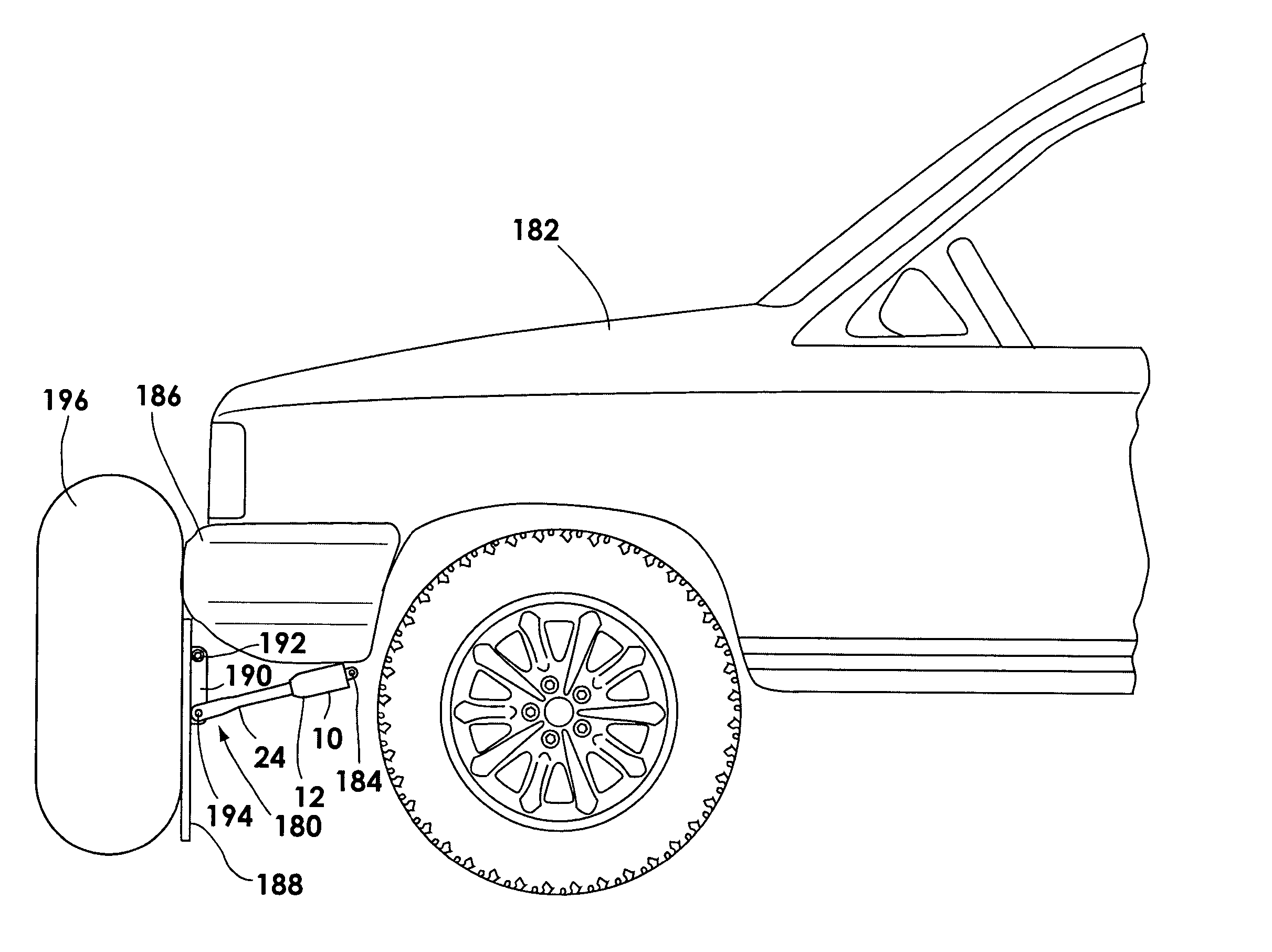
[0047] The presently preferred embodiments of the present invention will be best understood by reference to the drawings, wherein like parts are designated by like numerals throughout. It will be readily understood that the components of the present invention, as generally described and illustrated in the figures herein, could be arranged and designed in a wide variety of different configurations. Thus, the following more detailed description of the embodiments of the apparatus, system, and method of the present invention, as represented in FIGS. 1 through 8, is not intended to limit the scope of the invention, as claimed, but is merely representative of presently preferred embodiments of the invention.

[0048] Referring to FIG. 1, a cross-sectional view of the undeployed configuration of a linear actuator 10 having an internal dampening mechanism according to the present invention is illustrated. The actuator 10 comprises a housing 12 having a first end 14 and a second end 16. The h...


PUM


Abstract

A linear actuator with an internal dampening mechanism is disclosed. The actuator has a housing has a first end and a second end and forms an internal chamber. A constricted opening is also added to the actuator at the first end. A piston is disposed within the housing and is capable of sliding along the chamber. The piston has a head portion and a shaft portion. The shaft portion is slidable through the constricted opening whereas the head portion is not slidable through the constricted opening. A fluid is also added to the actuator. The fluid is disposed within the housing. In one embodiment, the actuator is constructed such that the sliding of the shaft portion forces a fluid through the constricted opening such that the movement of the piston is dampened. In an alternative embodiment, the actuator includes one or more second pistons and an orifice. In this embodiment, the actuator is constructed such that the sliding of the piston forces the fluid through the orifice and causes the second pistons to telescopically extend from the first piston.

Description

BACKGROUND OF THE INVENTION [0001] 1. Field of the Invention [0002] The present invention relates to linear actuators. More specifically, the present invention relates to a linear actuator with an internal dampening mechanism capable of adequately dampening the motion of the piston at the end of the stroke. [0003] 2. Description of the Related Art [0004] Linear actuators are well known as an efficient and very flexible mechanism for producing constant and uniform linear motion. As a result, they are commonly used in many industrial settings that require or involve linearly moving an object or load. Hydraulic lifts, such as the type found on most heavy equipment or machinery, are but one well-known example of the way in which linear actuators have been used in industry. [0005] A linear actuator comprises four main components: a housing, a piston (sometimes called a “piston rod”), a fluid, and a displacement mechanism (often called a “power supply”). In general, these components are a...

Claims


Application Information

Patent Timeline
IPC IPC(8): B60R19/32
CPCF15B15/19B60R19/32
Inventor LARSEN, ALAN R.SMITH, BRADLEY W.LINDSEY, DAVID W.
Owner AUTOLIV ASP INC
Why Eureka
Try Eureka