Wireless communication system for multi-carrier transmission, transmitter, transmission method, receiver, and reception method

a multi-carrier transmission and wireless communication technology, applied in the field of wireless communication systems, can solve the problems of complicated cabling, difficult lan construction, limited range of moving devices by cable length, etc., and achieve the effect of preventing intersymbol interference and preferable multi-carrier transmission

Inactive Publication Date: 2005-02-17
SONY CORP
View PDF6 Cites 30 Cited by
  • Summary
  • Abstract
  • Description
  • Claims
  • Application Information

AI Technical Summary

Benefits of technology

[0020] It is therefore an object of the present invention to provide a wireless communication system, a transmitter, a transmission method, a receiver, and a reception method capable of preferable multi-carrier transmission by providing a guard interval between transmission symbols so as to prevent intersymbol interference.

Problems solved by technology

Such wired LAN requires construction works for connections, making the LAN construction difficult and resulting in complicated cabling.
After the LAN is constructed, it has been inconvenient that the cable length limits the range of moving devices.
A multi-path causes a delay distortion (or frequency selective fading) to generate a communication error.
Intersymbol interference occurs due to the delay distortion.
If a multi-path component exists, however, a delayed wave affects the next symbol, causing intersymbol interference.
Further, there occurs an interference between subcarriers (inter-carrier interference), degrading reception characteristics.
If the wireless transmission is subject to an increase in the radiation power outside the signal band, this causes large interference with channels or other systems that use the band.
However, the restriction of bands loses part of the energy for transmission symbols.

Method used


Image

  • Wireless communication system for multi-carrier transmission, transmitter, transmission method, receiver, and reception method
  • Wireless communication system for multi-carrier transmission, transmitter, transmission method, receiver, and reception method
  • Wireless communication system for multi-carrier transmission, transmitter, transmission method, receiver, and reception method

Examples


Embodiment Construction

[0051] Embodiments of the present invention will be described in further detail with reference to the accompanying drawings.

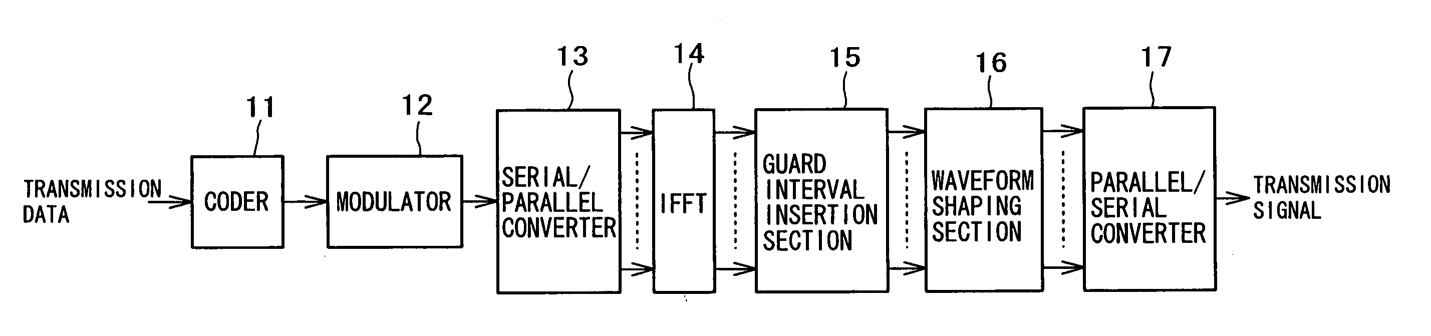
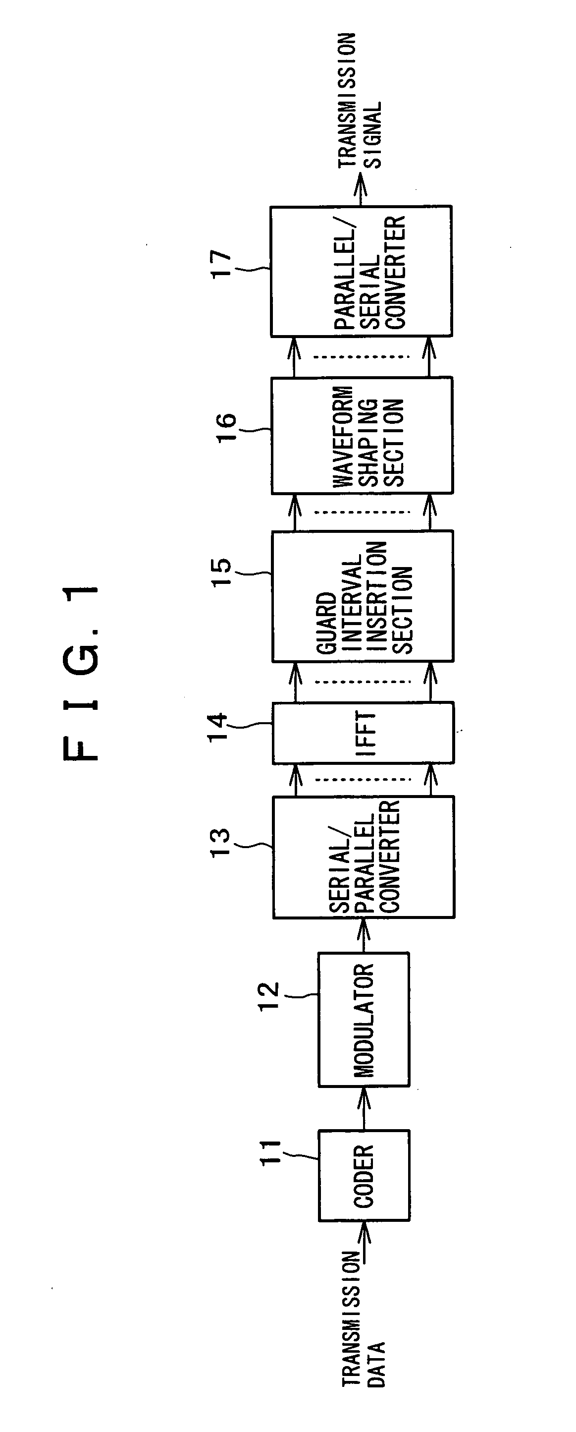
[0052] The present invention relates to a communication system using the OFDM system expected to be the technology that provides high-speed and high-quality wireless transmission. The OFDM system is one of multi-carrier transmission systems and configures carrier frequencies so that the carriers are allocated orthogonally to each other within a symbol region. A high-speed signal is divided into many subcarriers for transmission. As a result, a subcarrier alone is transmitted at a low speed. Accordingly, the system is resistant to interference of delayed waves.

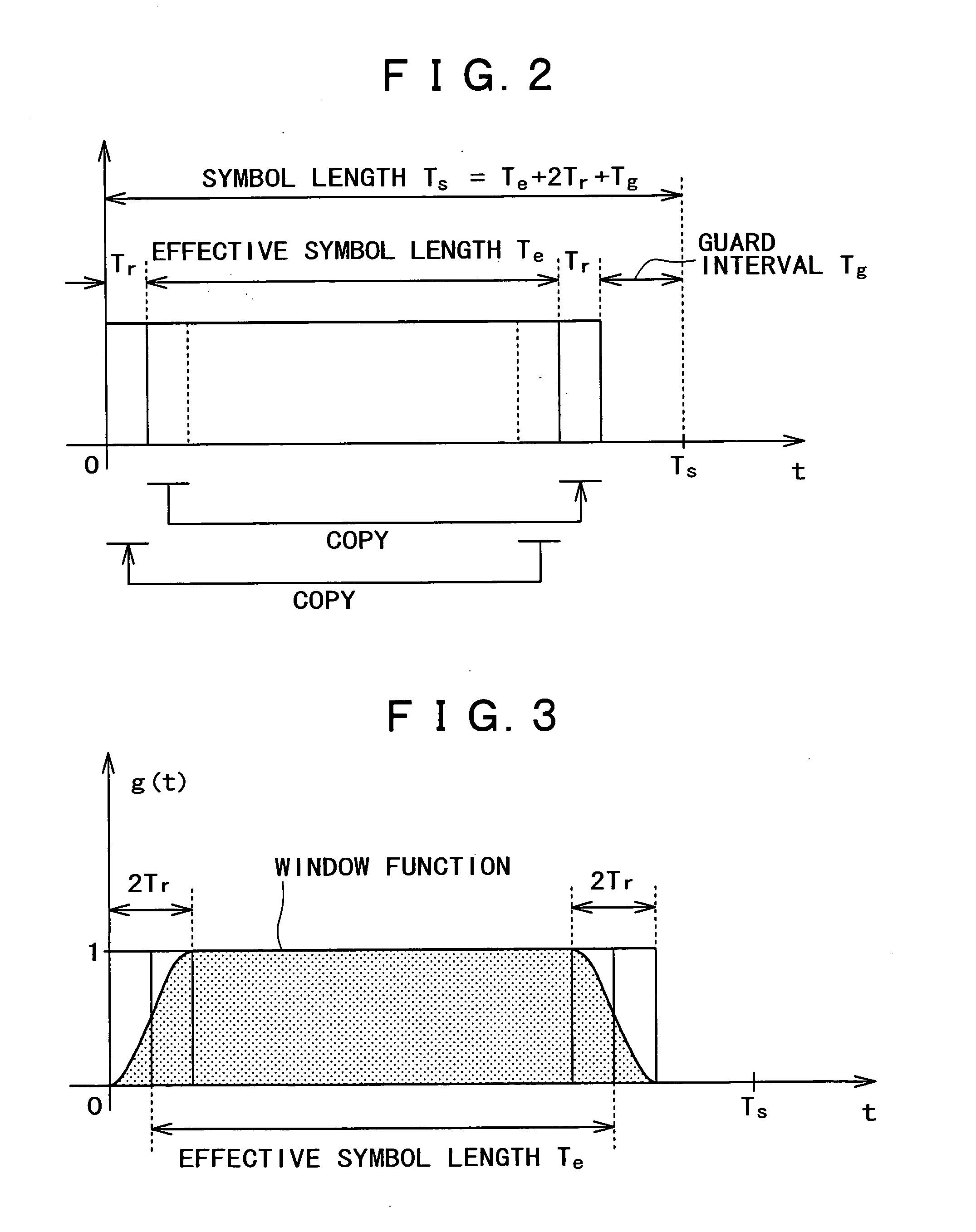
[0053] The OFDM transmission system provides a guard interval between transmission symbols to solve the problem of intersymbol interference under the multi-path environment. The system inserts guard signals such as a guard interval and a guard band into each transmission symbol in accordance with a speci...


PUM


Abstract

The present invention aims at configuring a guard interval period so as to control out-of-band radiation and decrease a transmission power loss. A transmitter provides a repetition signal for a very short time period at both ends of an effective symbol and copies the repetition signal to opposite sides of the effective symbol. The transmitter then inserts a null signal corresponding to a guard interval time to remove intersymbol interference. Further, a transmission signal is multiplied by a window function for waveform shaping. A window function value is configured so as to always keep constant the sum of the window function value and itself shifted by an effective symbol length. This prevents the transmission symbol's energy from exceeding the energy for the effective symbol length before multiplication of the window function.

Description

BACKGROUND OF THE INVENTION [0001] 1. Field of the Invention [0002] The present invention relates to a wireless communication system, a receiver, and a transmitter applicable to multi-path environments such as rooms where there are propagated a plurality of reflected waves and delayed waves including direct waves. Specifically, the present invention relates to a wireless communication system, a transmitter, a transmission method, a receiver, and a reception method so as to perform multi-carrier transmission by distributing transmission data into a plurality of carriers with different frequencies for the purpose of delay distortion solutions. [0003] In more detail, the present invention concerns a wireless communication system, a transmitter, a transmission method, a receiver, and a reception method for performing multi-carrier transmission by providing a guard interval between transmission symbols to prevent intersymbol interference. Specifically, the present invention relates to a ...

Claims


Application Information

Patent Timeline
Patent Type & Authority Applications(United States)
IPC IPC(8): H04J11/00H04L27/26
CPCH04L27/2607H04L27/2605
Inventor SUZUKI, MITSUHIROFUJITA, CHIHIRO
Owner SONY CORP
Why Eureka
Try Eureka