Phase detector for a phase-locked loop

a phase detector and phase-locked loop technology, applied in the field of phase detectors for phase-locked loops, can solve the problems of phase control corruption, phase-locked loop production in digital form, and emc radiation is more readily possible with such components,

Inactive Publication Date: 2007-07-10
THOMSON LICENSING SA
View PDF9 Cites 0 Cited by
  • Summary
  • Abstract
  • Description
  • Claims
  • Application Information

AI Technical Summary

Benefits of technology

[0014]If the recorded data signal is a ternary data signal, i.e. a data signal in which positive and negative signal components succeed one another, then it is very advantageous for the sampled and digitized data signal to pass through a rectifier stage first, for the purposes of signal conditioning. This converts the negative components of the data signal to positive components, and no problems arise with the subsequent difference formation / comparison operation.
[0015]To avoid “intersymbol interference” between adjacent signal components, it has also been found to be advantageous for positive and negative signal components in the data signal to be supplied, before rectification, to a separating stage which separates the data signal into a positive and a negative path. The two paths are then treated separately, i.e. the delay and subtraction stages and the associated processing stage for assigning data must be present for each path individually. Also, an addition stage is then necessary, in which the assigned output values from the two paths are added and, combined in this way, are passed on to the filter / control stage.

Problems solved by technology

However, high-quality analogue components need to be used when producing such a phase-locked loop, since ageing- and temperature-related component variations can otherwise very easily result in corruptions in the phase control.
A further disadvantage could also be that EMC radiation is more readily possible with such components if it is not prevented by complex shielding measures.
These disadvantages require that a phase-locked loop be produced in digital form.
The repetition rate of these patterns can be very low, however, so that long control times can result until the optimum clock frequency is set.

Method used


Image

  • Phase detector for a phase-locked loop
  • Phase detector for a phase-locked loop
  • Phase detector for a phase-locked loop

Examples


Embodiment Construction

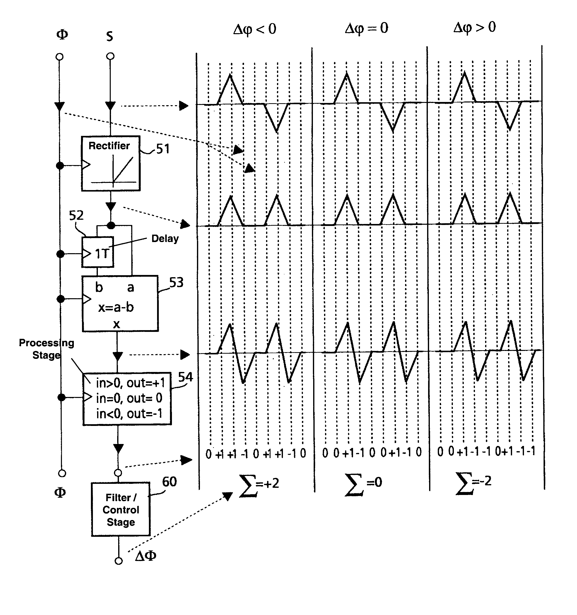
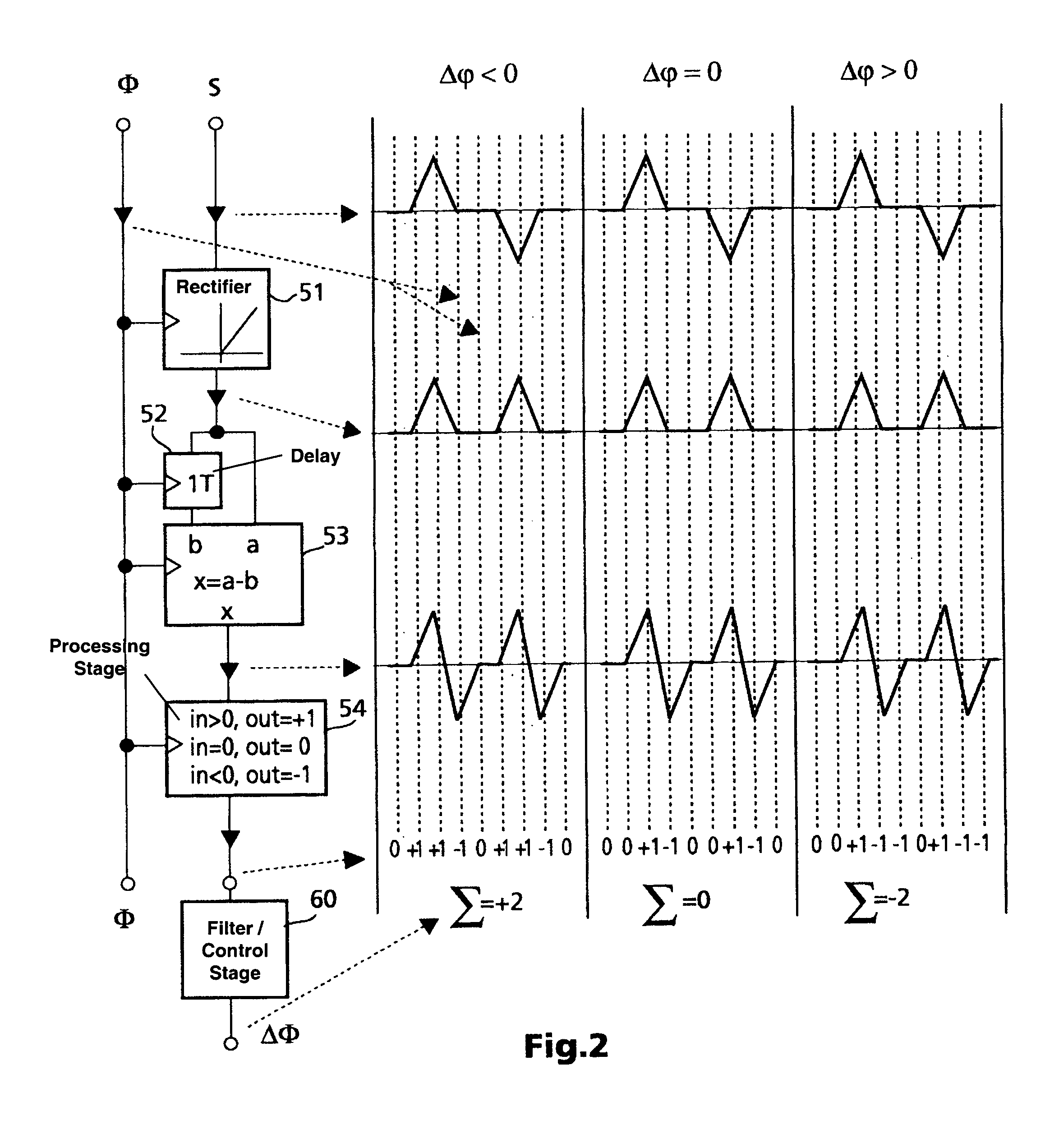
[0023]The phase detector according to the invention is intended to be used in a digital implementation of a phase-locked loop. Such PLL circuits can be used in diverse areas where, for example, the data digitally recorded on a storage medium needs to be recovered or else where a transmitted data stream is received whose data likewise needs to be recovered. The recorded or transmitted data signals are very frequently self-clocking, i.e. they are coded such that enough edges arise in the data signal for it to be possible to use conventional PLL circuits to recover the data clock signal reliably. The invention is therefore also explained in more detail below using the example of this important application instance.

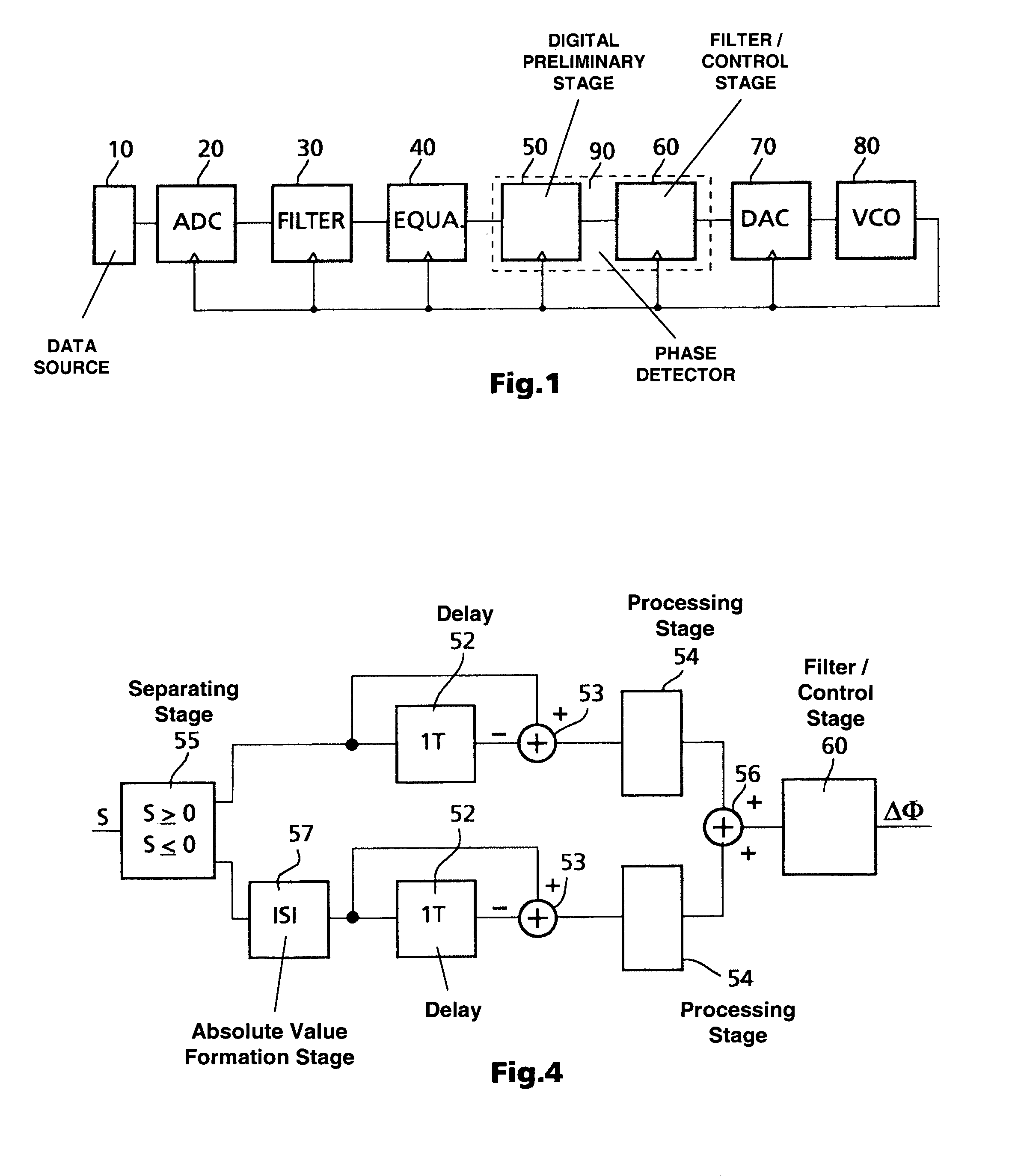
[0024]In FIG. 1, the reference numeral 10 denotes a data source. Known data recording units are, by way of example, digital video recorders based on the D-VHS standard, DVC units, DVD units, CD units, MD units etc. Examples of units which receive digitally transmitted data ar...


PUM

PropertyMeasurementUnit
temperatureaaaaaaaaaa
phaseaaaaaaaaaa
clock frequencyaaaaaaaaaa

Abstract

A phased-locked loop phase detector for digital input signals in which digital summed value for a particular number of bits is equal to zero. Sampled and digitized data comprising a delay stage for delaying the data signal by a one or more sampling clock period is supplied to the phase detector as an input signal. The delayed data signal and the undelayed data signal are then supplied to a subtraction stage. The difference between the two input values is formed in this subtraction stage. The processing stage assigns one of a plurality of possible values to the respective differential value. The full differential value range is subdivided in a number of sub-ranges corresponding to the plurality of possible values. All differential values in one sub-range are assigned the same output value. The output of the subtraction stage is supplied to a filter/control stage.

Description

[0001]This application claims the benefit, under 35 U.S.C. § 365 of International Application PCT / EP00 / 08064, filed Aug. 18, 2000, which was published in accordance with PCT Article 21(2) on Mar. 8, 2001 in English and which claims the benefit of German patent application No. 19941445.9 filed Aug. 30, 1999.[0002]The invention relates to a phase detector for a phase-locked loop. In particular, the phase detector is intended to be used for a phase-locked loop which is used for recovering the data clock signal in a recorded or transmitted data signal. The recorded or received data signal implicitly contains the data clock signal and is thus self-clocking.PRIOR ART[0003]The invention is based on a phase detector for a phase-locked loop according to the generic type in the independent claim 1. Phase-locked loops are widely described in the prior art. As an example, reference is made to U.S. Pat. No. 5,693,376, which describes a programmable phase-locked loop which is likewise used for re...

Claims


Application Information

Patent Timeline
Patent Type & Authority Patents(United States)
IPC IPC(8): H03D3/24G11B20/14H03K5/26H03L7/085H03L7/091H04L7/033
CPCG11B20/10037G11B20/1403H03L7/085H03L7/091G11B20/1024G11B20/1423
Inventor WURSTHORN, EDGAR
Owner THOMSON LICENSING SA
Why Eureka
Try Eureka