Method for symbol synchronization of received digital signal and digital signal receiver using the same method

a digital signal and receiver technology, applied in the field of digital signal receiving technology, can solve the problems of wasting resources, wasting resources, and wasting resources, and achieve the effects of reducing the symbol timing error of the receiver, avoiding inter-symbol interference (isi), and efficient detection

Active Publication Date: 2015-08-11
INTERDIGITAL MADISON PATENT HLDG
View PDF31 Cites 0 Cited by
  • Summary
  • Abstract
  • Description
  • Claims
  • Application Information

AI Technical Summary

Benefits of technology

[0017]Since the strongest path affection is removed, the fastest path can be detected efficiently in a simple algorithm, advantageously, the timing of the fastest path is used in the symbol synchronization under the multi-path environment, therefore the symbol timing error of the receiver is reduced, and Inter-Symbol Interference (ISI) will be avoided.

Problems solved by technology

But in long path channel such as Single Frequency Network (SFN) channel, especially two-path channel whose first arrived path is not the strongest one and the strongest path is far away from the first path, even its channel delay over a guard interval, the conventional estimation algorithm gives a little effort.
It only estimates position of average peak or maximum peak, as the result, symbol timing error of the receiver is very big.
As the result, the first useful path is still discarded.
If the distance of two path reaches guard interval or even larger, the error will be larger.
However, it's still methodologically complicated, so that the memory resource needs for the computation is high.

Method used


Image

  • Method for symbol synchronization of received digital signal and digital signal receiver using the same method
  • Method for symbol synchronization of received digital signal and digital signal receiver using the same method
  • Method for symbol synchronization of received digital signal and digital signal receiver using the same method

Examples


Embodiment Construction

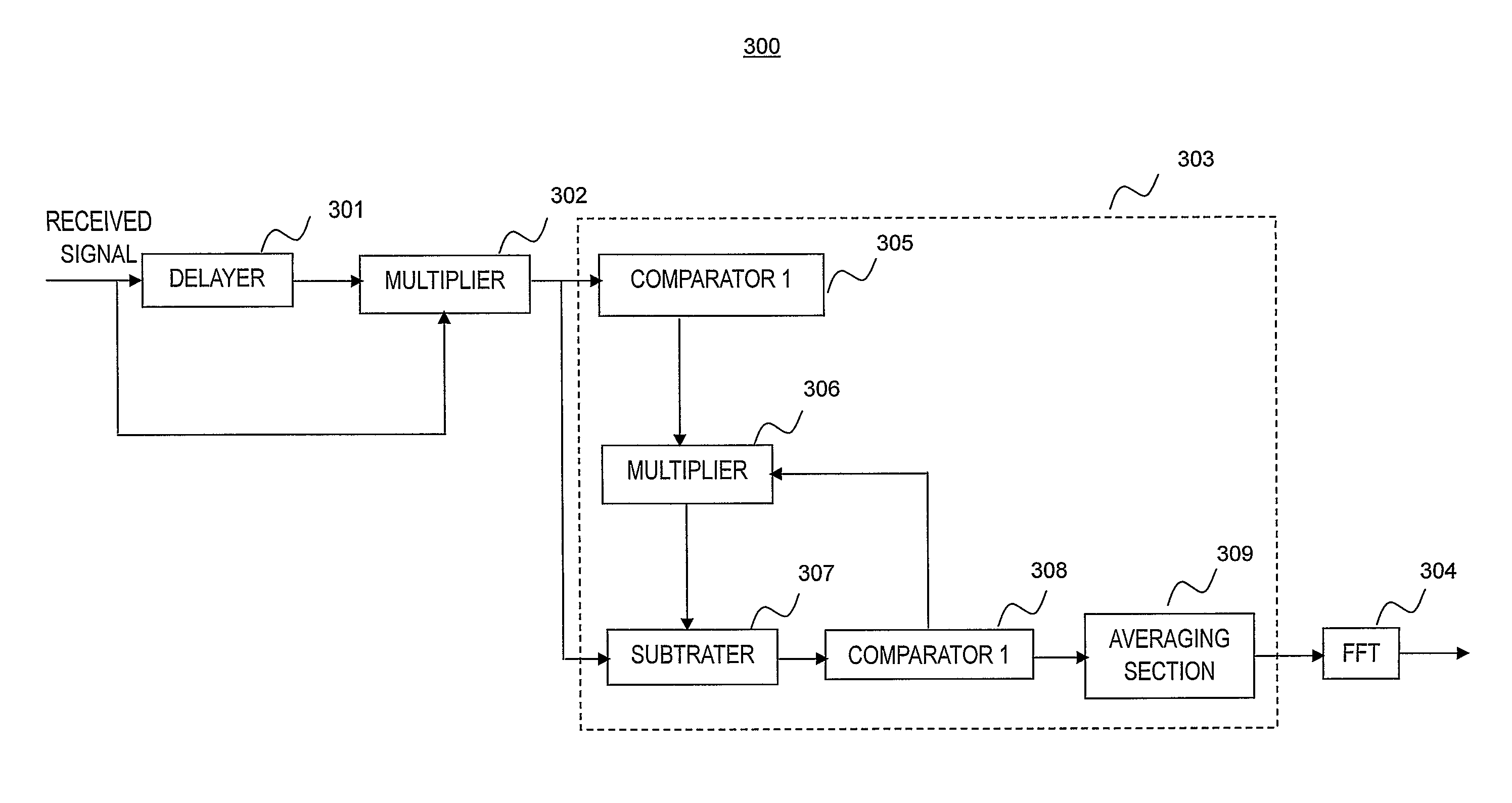
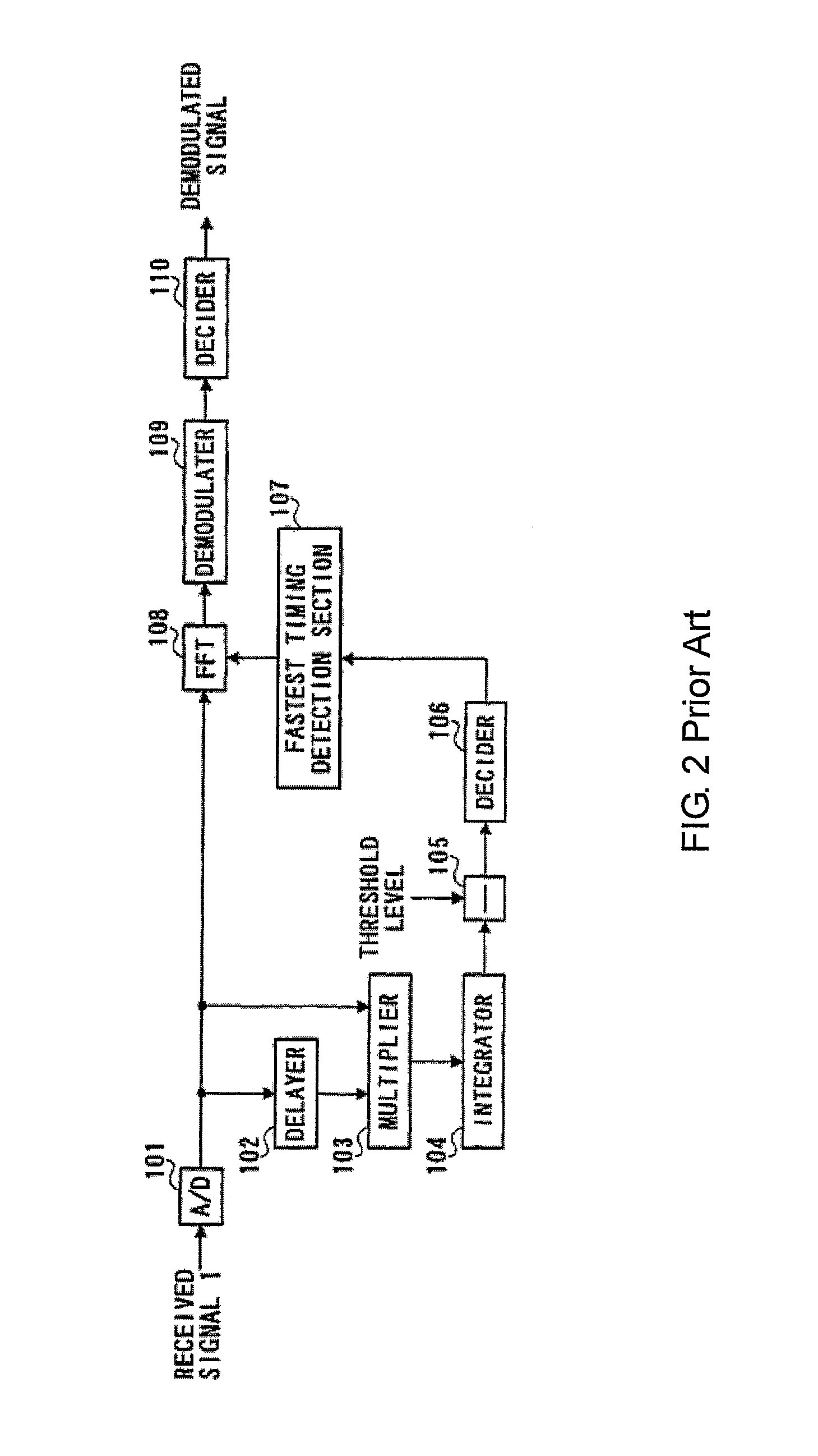
[0025]The present invention provides an improved symbol synchronization method for digital signal reception and a digital signal reception apparatus using this method. The gist of the invention is to use the fastest symbol synchronization timing for initiation of processing the FFT, characterized by the way of removing the effect of the strongest path. Embodiments of the present invention will now be described with reference to accompanying drawings.

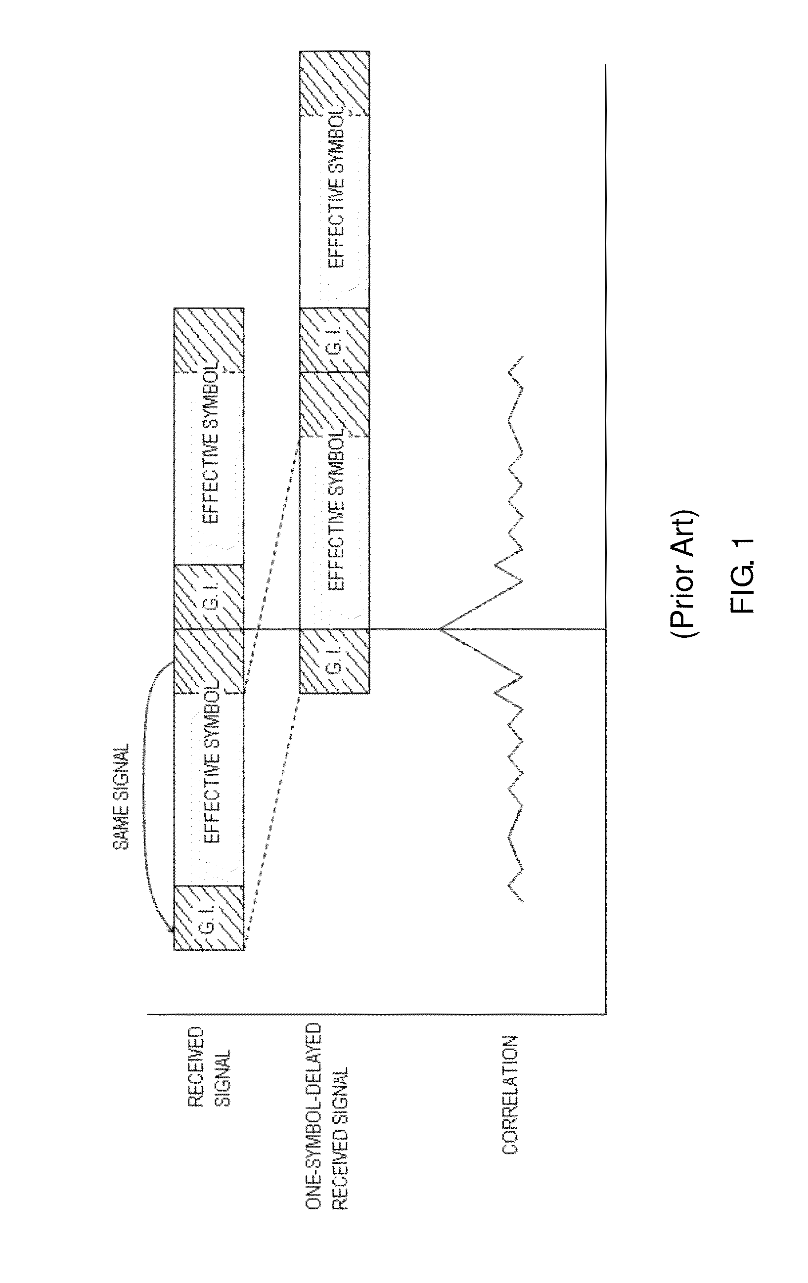
[0026]Considering one channel model which comprises two paths and the first arrived path may not be the strongest one, the main idea of the invention is to remove the effect of the strongest path, and use a threshold as an estimation standard. With reference to FIG. 4, an exemplary diagram of correlation value of the received signal and the received signal delayed by one symbol based on DVB-T system frame structure (2 k mode) is shown. Where, channel delay is [0 60] us, relative channel power is [−5 0] dB, Maximum Doppler frequency is 50...


PUM


Abstract

A method for symbol synchronization of received digital signal and a digital signal reception apparatus are provided. The method comprises steps of correlating the received digital signal with the received signal delayed by one symbol so as to obtain a first correlation value result as a combined effort of a strongest path and other paths; removing substantially effect of the strongest path from the first correlation result so as to obtain a second correlation result which exhibits contribution of a fastest path; searching a maximum correlation value and its position of the fastest path so as to determine symbol synchronization timing for initiating FFT processing. The digital signal reception apparatus is characterized by a symbol timing detecting unit for determining symbol synchronization timing of the fastest path through substantially removing the effect of a strongest path.

Description

[0001]This application claims the benefit, under 35 U.S.C. §365 of International Application PCT / CN2007 / 000183 , filed Jan. 18, 2007, which was published in accordance with PCT Article 21(2) on Jul. 31, 2008 in English.FIELD OF THE INVENTION[0002]The present invention relates to digital signal receiving technology, and more particularly to a method for symbol synchronization of received digital signal and a digital signal receiving apparatus using the same method.BACKGROUND OF THE INVENTION[0003]Synchronization is one crucial subject for digital signal receiving system, which includes symbol timing, frequency synchronization and sample clock synchronization in OFDM system. For the symbol timing which determines the Fast Fourier Transform (FFT) placement location, the proper selection of this location has a major performance impact on all post FFT algorithms. Therefore, it is desirable to achieve good timing early in the acquisition.[0004]In some current systems, e.g. the Orthogonal ...

Claims


Application Information

Patent Timeline
Patent Type & Authority Patents(United States)
IPC IPC(8): H04L7/00H04L27/26H04L69/14
CPCH04L27/2662H04L27/2678H04L27/2688H04L69/14
Inventor LIU, GANGZOU, LI
Owner INTERDIGITAL MADISON PATENT HLDG
Why Eureka
Try Eureka