Handling large, heavy workpieces using coordinated gantry robots

Inactive Publication Date: 2005-02-17
FANUC ROBOTICS NORTH AMERICA
View PDF17 Cites 60 Cited by
  • Summary
  • Abstract
  • Description
  • Claims
  • Application Information

AI Technical Summary

Benefits of technology

[0007] The present invention provides a coordinated, six-axis gantry robot having high load capacity with orientation control to manipulate large, heavy workpieces. An elevated ra

Problems solved by technology

Individual heavy-payload robots typically require very large tooling to engage large workpieces, severely eroding available payload capacity for the workpiece, and the gripper design is highly engineering intensive.
Such robots have limited reach if they are fixed to the floor, and they cannot achieve large transfer distances when handling large workpieces.
To achieve large transfer distances individual heavy-payload robots present sizable physical obstacles at floor level if mounted to a floor, rail, or track.
They cannot adapt easily to a variety of workpiece sizes, and may require additional tooling or changeover adjustment to reposition tooling structure and components.
Custom transfer automation equipment is custom-engineered for each application, requiring intensive engineering effort, and lengthy lead-time.
This equipment is inflexible, or requires high complexity to achi

Method used


Image

  • Handling large, heavy workpieces using coordinated gantry robots
  • Handling large, heavy workpieces using coordinated gantry robots
  • Handling large, heavy workpieces using coordinated gantry robots

Examples


Example

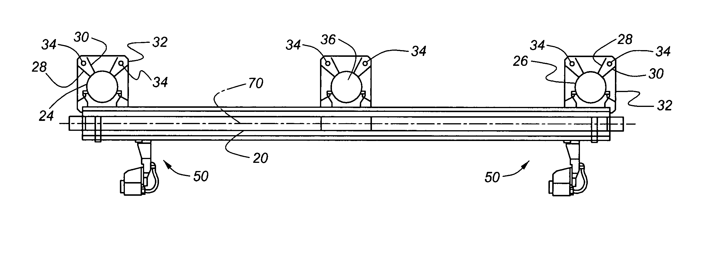
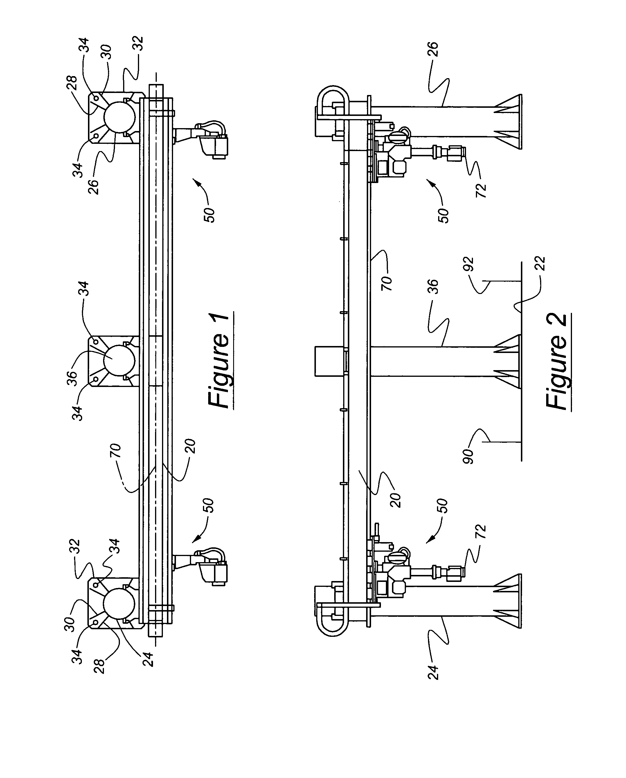
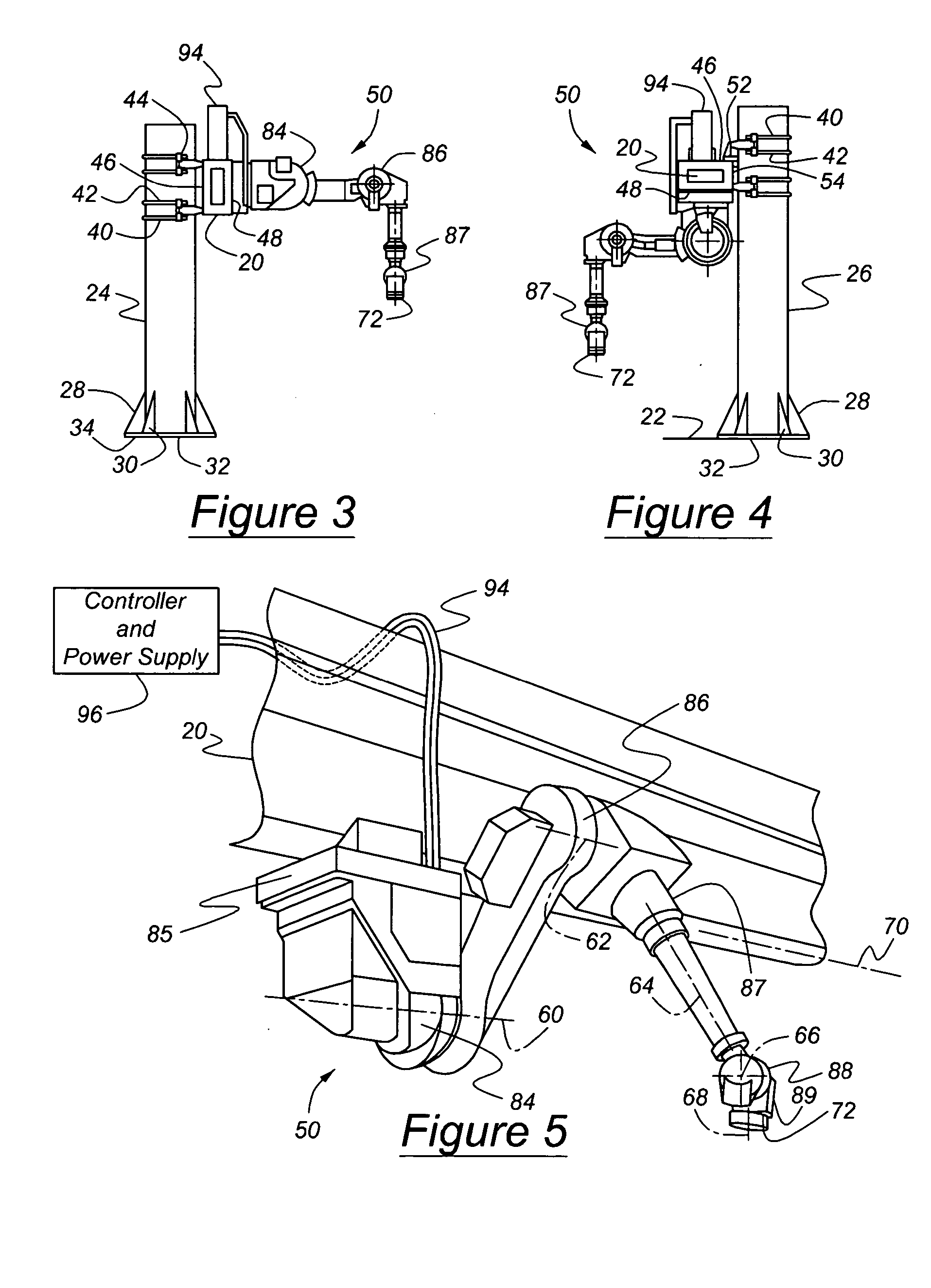
[0021]FIGS. 1-4 illustrate a rail 20 suspended above a workspace on the floor 22 of an industrial plant. The rail 20 is supported near each end by a column 24, 26, which is preferably in the form of a circular, cylindrical hollow tube. Located at the base of each column and extending radially from the column are pairs of flanges 28, 30, which are welded to the column and to a base plate 32. Bolts 34, located around the perimeter of the base plate 32, secure the base plate 32 to the floor 22 or to a footing located at or near the plane of the floor. When the span between the columns 24, 26 exceeds a predetermined length, at least one additional column 36, located between the end columns 24, 26, can be used to provide intermediate support to the rail 20.

[0022]FIGS. 3 and 4 show the rail 20 secured to and spaced a short distance from the columns 24, 26 by pairs of U-bolts 40, 42, which engage the circular cylindrical contour of the columns and are secured by fasteners 44 threaded onto...


PUM


Abstract

A robot system for handling and transporting workpieces in a workspace includes a rail supported above a floor, at least two robot arms supported on the rail for mutual relative displacement and coordinated displacement along the rail, each arm articulating about multiple axes for engaging and supporting the workpiece, and a controller communicating with each of the robot arms to control displacement and articulation of each robot arm, whereby the workpiece is engaged by each gripper, lifted on the robot arm, carried along a path, which may include motion along the rail, and released from the gripper at its destination.

Description

CROSS-REFERENCE TO RELATED APPLICATION [0001] This application claims the benefit of U.S. Provisional Application No. 60 / 488,668, filed Jul. 18, 2003, the entire disclosure of which is incorporated herein by reference.BACKGROUND OF THE INVENTION [0002] The subject invention generally relates to material handling of workpieces with a coordinated gantry. More specifically, the invention pertains to a system including a plurality of robots moveable along a rail. A single rail may support multiple robots, or each robot may be mounted on a separate rail. [0003] Custom transfer automation equipment, heavy-duty area gantries and heavy-payload pedestal robots employ well known, conventional techniques for transporting large, heavy workpieces over short distances, as required on a plant floor. [0004] Individual heavy-payload robots typically require very large tooling to engage large workpieces, severely eroding available payload capacity for the workpiece, and the gripper design is highly e...

Claims


Application Information

Patent Timeline
IPC IPC(8): B25J9/00B25J9/02B25J9/04B25J9/16
CPCB25J9/0084B25J9/026G05B2219/40293B25J9/1682G05B2219/39124B25J9/046
Inventor JHAVERI, NISHANTMISRA, RANGANATHORR, IAN H.MOTLEY, RICHARD M.
Owner FANUC ROBOTICS NORTH AMERICA
Why Eureka
Try Eureka