Non-migrating floor mat

a floor mat and non-migration technology, applied in the field of non-migration floor mats, can solve the problems of creating tripping hazards, additional labor and time to return the mats, and the approach did not prevent the displacement of the mats on smooth floors, so as to improve the stability of the floor, improve the stability, and improve the effect of structural sound

Inactive Publication Date: 2005-02-17
MILLIKEN & CO
View PDF7 Cites 16 Cited by
  • Summary
  • Abstract
  • Description
  • Claims
  • Application Information

AI Technical Summary

Benefits of technology

[0010] A feature of the present invention is the use of a mat having a plurality of depressions along the bottom surface of the mat. These depressions effectively secure the mat to surfaces once an initial force is applied. Additionally, the depressions do not results in a wavy mat surface such as most mats including suction cups. Because the depressions do not have a thin edge such as most suction cups, but are instead molded into the bottom of the mat, the depressions are also able to better retain their shape and are more structurally sound thereby making the mat more durable.
[0011] Another feature of the present invention is the use of a mat having a plurality of depressions with a particular pattern. This pattern prevents the edges of the mat from curling up or wrinkling, because there is a greater concentration along the edges of the mat.
[0012] Still another feature of the present invention is the use of mat having a smooth bottom surface. The smooth surface results in a higher coefficient of friction and facilitates suction because the floor surface contact is increased. Accordingly, the movement of the mat along the surface is minimized.
[0013] Yet another feature of the present invention is the use of mat formed from a soft, low durometer rubber material. The softness of the rubber enhances the effectiveness of both the depressions and the smooth backing of the mat in securing the mat to a surface.

Problems solved by technology

This movement can ultimately create tripping hazards.
Further, additional labor and time must be spent to return the mats to their appropriate positions.
However, this approach did not prevent displacement of the mats on smooth floors, especially those floors with high traffic areas or loads being moved on them.
However, these approaches add cost to the mats, as well as difficulty to the installation.
Furthermore, such systems can damage the surface onto which a mat is secured.
While this approach provides acceptable slip-resistance for applications involving lower traffic and lower load areas, such as bathrooms and showers, these suction cups do not provide sufficient anti-skidding forces to prevent slipping and movement in high traffic and high load areas such as grocery stores.
Furthermore, traditional suction cups result in a wavy mat surface, which may be more difficult for individuals and loads to traverse.

Method used


Image

  • Non-migrating floor mat
  • Non-migrating floor mat
  • Non-migrating floor mat

Examples


example 1

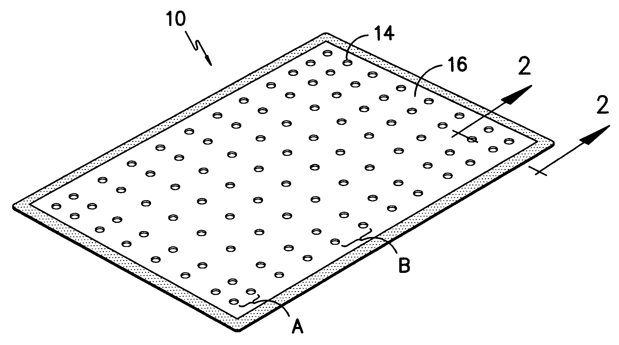
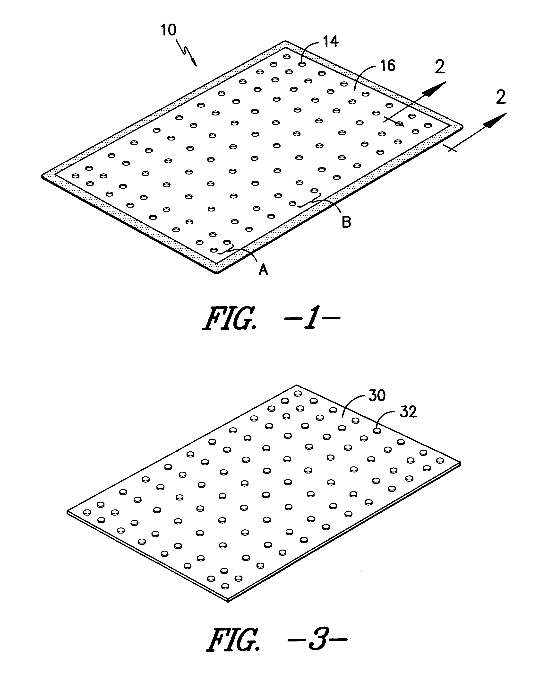
[0029] A first mat having a mat size of 3 feet by 10 feet, weighing approximately 21 lbs., and having the features described above, including a base layer made of rubber that is bonded to a top layer of fabric, a smooth bottom surface, and a plurality of depressions having diameter of approximately 1 inch and a depth of approximately 0.125 inches, was subjected to the Kex Walk Test as described above. The mat was first washed with a non-ionic detergent at 140° F. Thereafter, the mat was placed on a hard tile floor surface over tape markers. Next, a walker pushing a grocery cart that was loaded to give the cart a total weight of 100 lbs. passed over the mat 50 times.

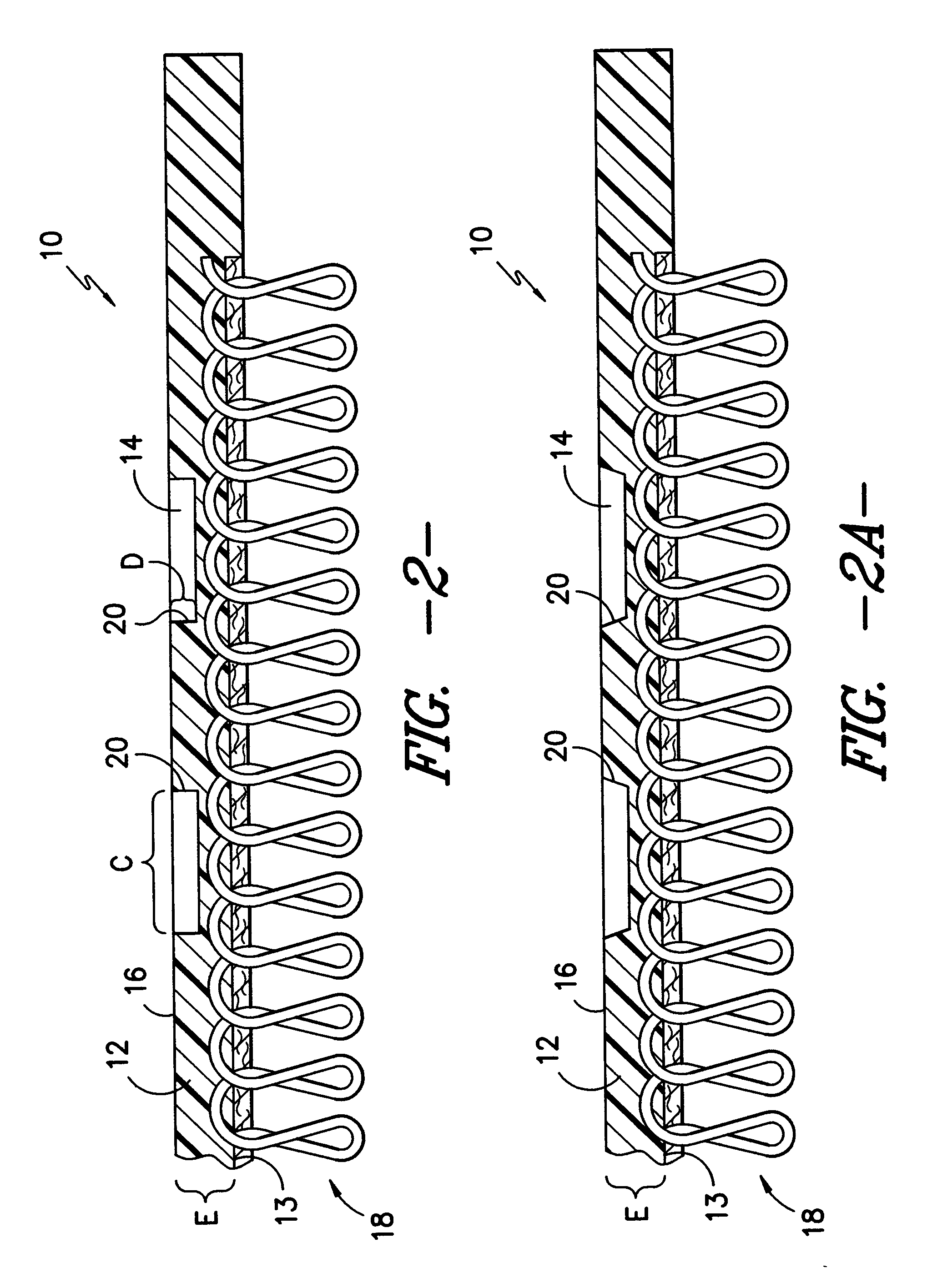
[0030] Comparatively, a second mat having a mat size of 3 feet by 10 feet and weighing approximately 12 lbs. was also subjected to the same Kex Walk Test. The second mat also included a base layer of rubber bonded to a top layer of fabric. However, the second mat did not include a smooth bottom surface and a plurality of...


PUM

PropertyMeasurementUnit
Lengthaaaaaaaaaa
Lengthaaaaaaaaaa
Thicknessaaaaaaaaaa

Abstract

A mat having a base layer that is bonded to a top layer. The base layer of the mat includes a plurality of depressions along the bottom surface of the base layer, wherein the depth of the depressions does not exceed the depth of the base layer. The orientation of the depressions on the bottom surface of the mat is such that there is a greater concentration of depressions along the edges of the mat. The top layer of the mat is preferably a layer of carpet tuft. In operation, the depressions of the mat suction the mat to the surface onto which the mat is placed once an initial force is applied to the mat, such as a footstep or vehicular traffic.

Description

BACKGROUND OF THE INVENTION [0001] The present invention relates generally to slip resistant mats, and, more particularly, to mats having suction cups on the underside of the mats. [0002] It is well known that rubber-backed floor mats tend to move along surfaces, such as wood, concrete, or tile, when walked upon. This movement can ultimately create tripping hazards. Further, additional labor and time must be spent to return the mats to their appropriate positions. Accordingly, various slip resistant or anti-skid features have been employed in the past to overcome these problems. [0003] Historically, cleats have been added to the bottom surface of the mats so that the mats can better grip the surfaces onto which they are placed and thereby reduce their movement. [0004] However, this approach did not prevent displacement of the mats on smooth floors, especially those floors with high traffic areas or loads being moved on them. This displacement results from the force of foot and vehic...

Claims


Application Information

Patent Timeline
IPC IPC(8): A47G27/04B32B25/10D06N7/00
CPCA47G27/0225B32B25/10D06N2203/042D06N2211/066Y10T428/24479D06N7/0076D06N2203/047D06N2203/02D06N2213/061D06N7/0068B32B2307/536B32B3/30B32B2307/744B32B2323/16B32B2471/04
Inventor STREETON, AMY B.BURKE, WILLIAM O.
Owner MILLIKEN & CO
Why Eureka
Try Eureka