Chain drive system

Inactive Publication Date: 2005-02-17
NISSAN MOTOR CO LTD
View PDF99 Cites 30 Cited by
  • Summary
  • Abstract
  • Description
  • Claims
  • Application Information

AI Technical Summary

Benefits of technology

[0007] It is therefore an object of the present invention to provide a chain drive system having opposite parts sliding on each other with less friction resistance and wear so as to prevent energy loss and noise and to increase in durability for improvements in the operation performance and efficiency of any instrument, such as an internal combustion engine, equipped with the chain drive s

Problems solved by technology

Due to the sliding friction between the pin and the chain plate and between any two adjacent chain plates, however, there arise various problems such as energy loss, noise, wear and chain elongation.
In addition, the performance deteriorations (such as control timing delay) of the chain drive system may be caused by the chain elongation.
When the sliding friction between the tensioner body and the plunger is increased, the tensioner body and the plunger become subjected to severe w

Method used


Image

  • Chain drive system
  • Chain drive system
  • Chain drive system

Examples


Embodiment Construction

[0019] The present invention will be described below in detail. In the following description, all percentages (%) are by mass unless otherwise specified.

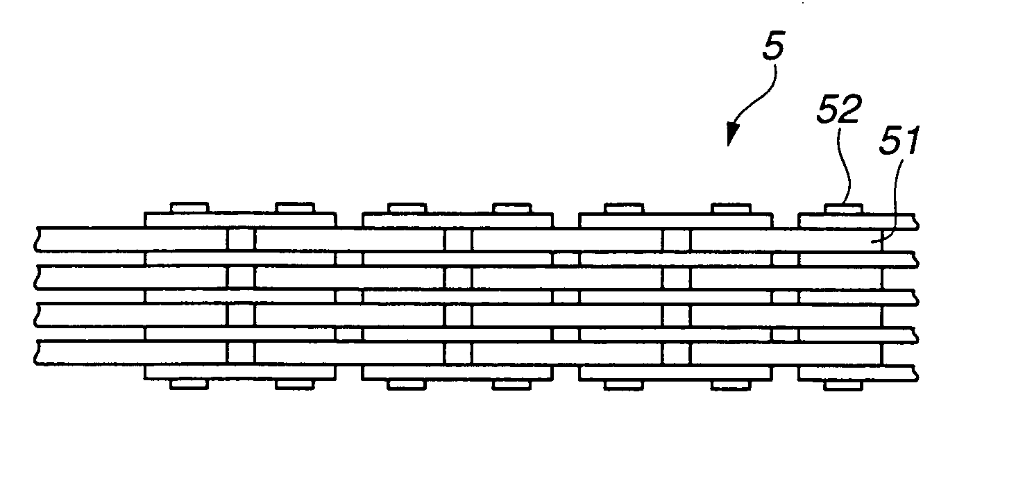
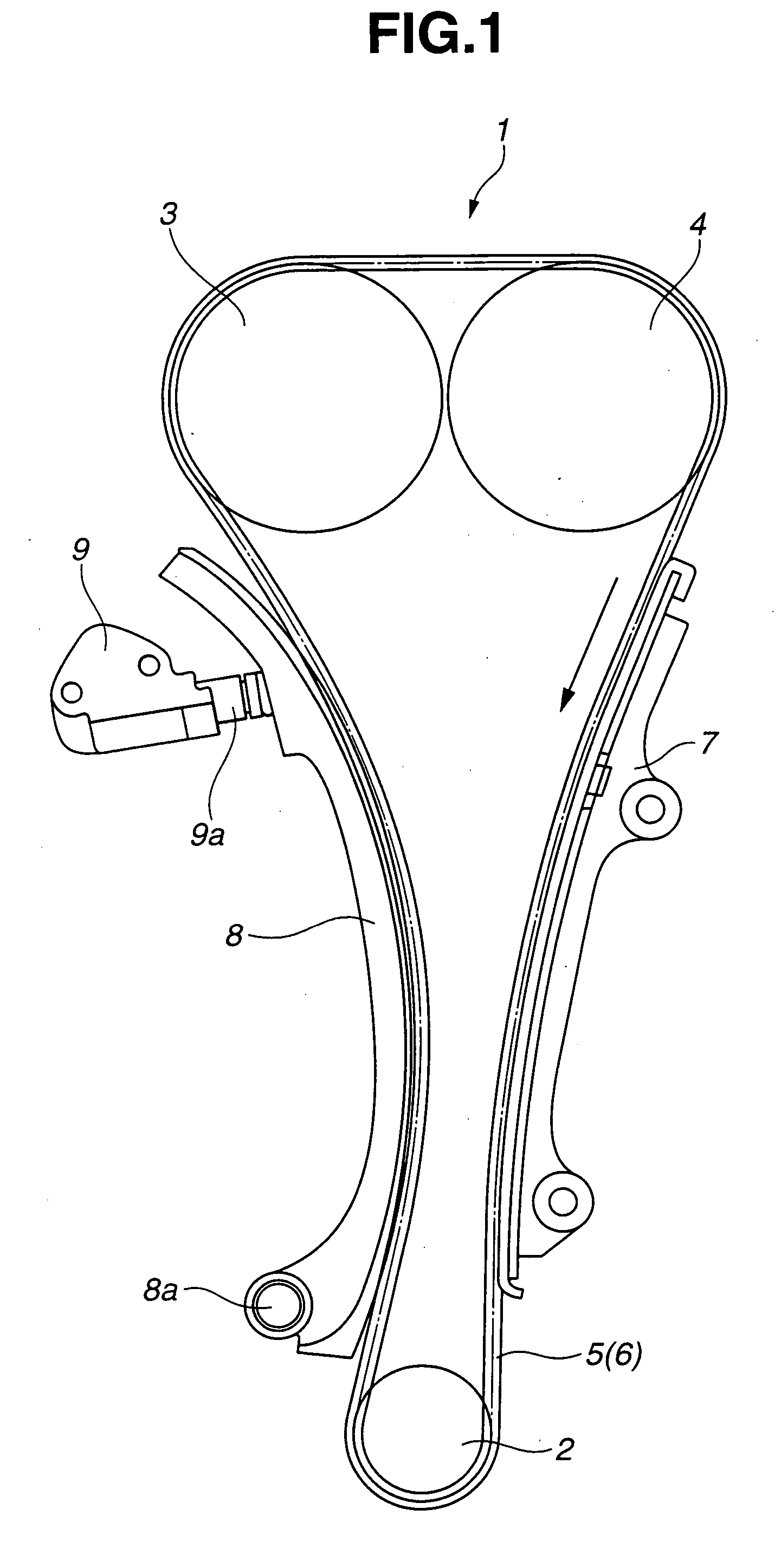
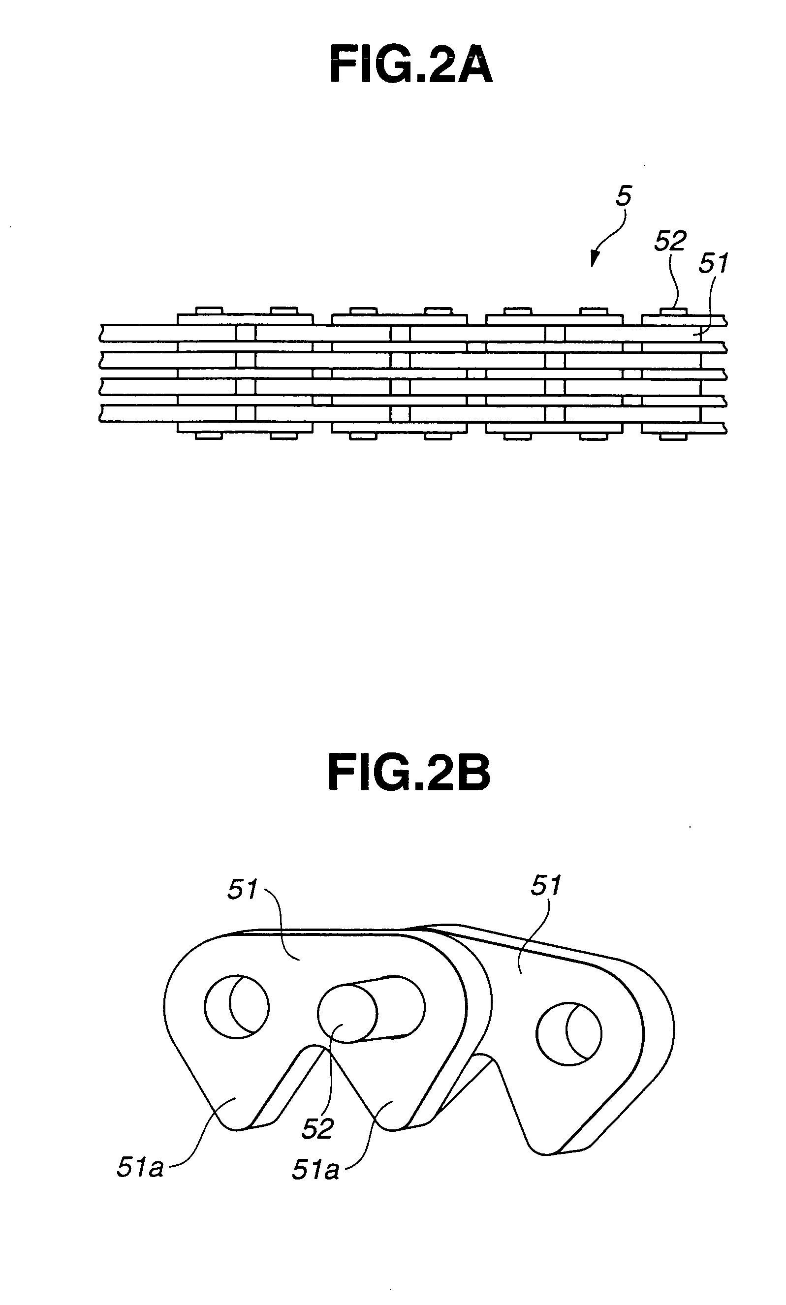
[0020] As shown in FIG. 1, chain drive system 1 according to one exemplary embodiment of the present invention includes first sprocket 2 (as a drive sprocket), a pair of second and third sprockets 3 and 4 (as driven sprockets) and silent chain 5 or roller chain 6. Chain 5 or 6 is formed with chain components and looped over first and second sprockets 2, 3 and 4 so as to move in a chain driving direction (as indicated by an arrow in FIG. 1). Chain drive system 1 further includes chain guide 7 and a chain tensioner unit provided with slack guide 8 and tensioner 9 to control a tension applied to chain 5 or 6, as shown in FIG. 1. Chain guide 7 is disposed between first and third sprockets 2 and 4 to guide the movement of chain 5 or 6 in the chain driving direction properly. Slack guide 8 is disposed between first and second sprockets 2...


PUM


Abstract

A chain drive system includes a drive sprocket, a driven sprocket and a chain looped over the drive sprocket and the driven sprocket. The chain and the sprocket having respective sliding surfaces slidable relative to each other in the presence of lubricating oil, and any adjacent chain components of the chain having respective sliding surfaces slidable relative to each other in the presence of lubricating oil. At least one of the sliding surfaces between the chain and the sprocket and at least one of the sliding surfaces between any adjacent chain components have hard carbon coatings formed on base portions thereof. Each of the hard carbon coatings has a hydrogen content of 10 atomic % or less.

Description

CROSS-REFERENCE TO RELATED APPLICATIONS [0001] The present application is related to the following applications: U.S. patent application Ser. No. 09 / 545,181 (based on Japanese Patent Application Hei-11-102205 filed on Apr. 9, 1999); U.S. patent application Ser. No. 10 / 468,713, which is the national phase of PCT Application No. JP02 / 10057 (based on Japanese Patent Application 2001-117680 filed on Apr. 17, 2001); U.S. patent application Ser. No.10 / 355,099 (based on Japanese Patent Application 2002-45576 filed on Feb. 22, 2002); U.S. patent application Ser. No. 10 / 682,559 (based on Japanese Patent Application No. 2002-302205 filed on Oct. 16, 2002); and U.S. patent application Ser. No. 10 / 692,853 (based on Japanese Patent Application 2002-322322 filed on Oct. 16, 2002).BACKGROUND OF THE INVENTION [0002] The invention relates to a chain drive system having parts sliding on each other with less friction resistance and wear so as to increase in durability, prevent secular deteriorations i...

Claims


Application Information

Patent Timeline
IPC IPC(8): F16H7/18F16C5/00F16C9/04F16C33/16F16G13/02F16G13/06F16H7/08
CPCF16C5/00F16C9/04F16H57/041F16G13/06F16C33/16C10M2207/289C10N2030/06C10N2040/25C10N2080/00
Inventor MURATA, TAKASHIHIRATA, TAKUYAKANO, MAKOTOMABUCHI, YUTAKAHAMADA, TAKAHIROYAMAGUCHI, MASASHI
Owner NISSAN MOTOR CO LTD
Why Eureka
Try Eureka