Temperature sensing device for metering fluids

a temperature sensing device and fluid technology, applied in the direction of instruments, heat measurement, volume/mass flow by differential pressure, etc., can solve the problems of inaccurate temperature measurement of flowing medium, substantial monetary sums being paid or not paid for delivered gas, inaccurate calculation of flow volume by the meter which includes a computer processing unit (cpu), etc., to improve the rate of temperature transfer, improve the temperature conductivity, and improve the effect of surface area

Inactive Publication Date: 2005-02-17
PARKER INTANGIBLES LLC
View PDF10 Cites 44 Cited by
  • Summary
  • Abstract
  • Description
  • Claims
  • Application Information

AI Technical Summary

Benefits of technology

[0008] The present invention is directed to a thermowell assembly extending within a metallic fluid conduit in a direction perpendicular to the direction of flow to a position past the axial centerline of the metallic conduit. The thermowell assembly includes a temperature sensing probe received within an outer metallic sheath or closed tube. The outer metallic tube which has a closed inner end is exposed to the fluid flowing through the conduit and a plurality of spaced annular ribs or fins extend within the conduit about the outer periphery of the tube for improved temperature conductivity to the temperature sensing probe. The relatively large surface area of the fins improves the rate of temperature transfer by the fins.

Problems solved by technology

If the temperature of the fluid medium is not correct, the calculated flow volume by the meter which includes a computer processing unit (CPU) will be inaccurate.
In measuring the gas flow through a gas pipeline, for example, in which the gas flow volume is utilized to effect payment of gas being purchased, an inaccuracy in the temperature of the flowing gas may result in substantial monetary sums being paid or not being paid for delivered gas resulting from an error in the temperature of the flowing gas.
Variations in temperature of the exposed pipeline sections results in a temperature conduction from the metallic pipeline to the metallic thermowell assembly which may result in an inaccurate temperature measurement of the flowing medium.
Thus, temperature from the pipe exposed to ambient conditions is conducted to the outer tube of the thermowell which may result in an error in the temperature of the fluid flow under certain conditions.

Method used


Image

  • Temperature sensing device for metering fluids
  • Temperature sensing device for metering fluids
  • Temperature sensing device for metering fluids

Examples


embodiment

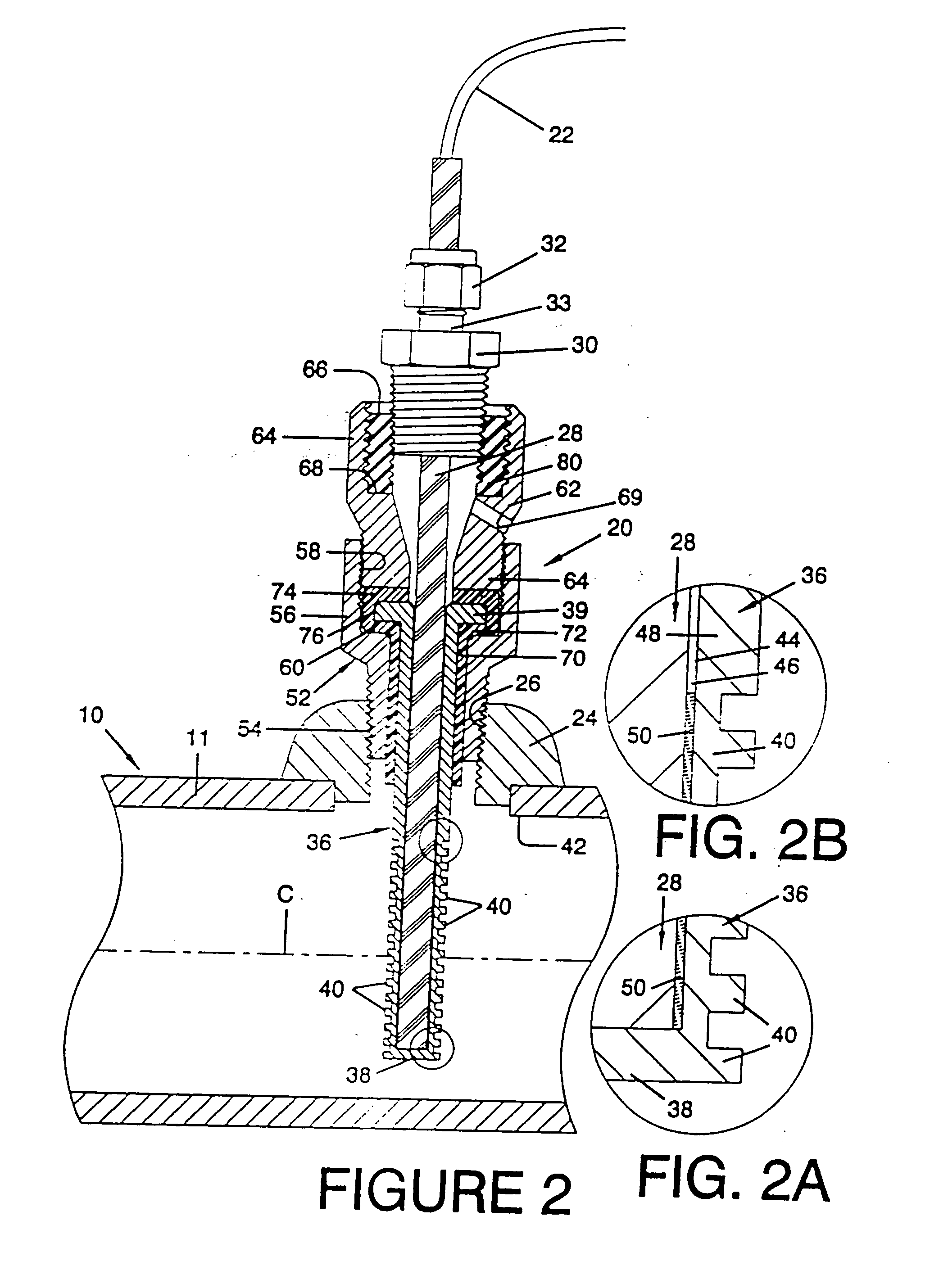
[0044] Embodiment of FIG. 2

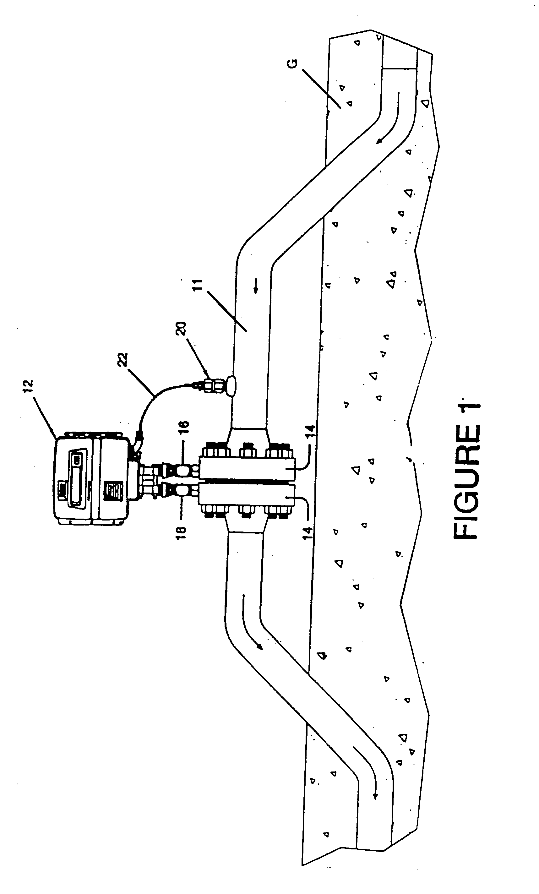
[0045] Referring now particularly to the embodiment of FIG. 2, a thermowell assembly generally indicated at 20 is illustrated as mounted on pipeline section 11 of pipeline 10 above the ground. Pipeline section 11 has a mounting weld flange 24 secured thereon and having internal threads 26 defining a central bore. Thermowell assembly 20 includes a TSP generally indicated at 28 having an externally threaded upper mounting plug 30. TSP 28 consists of various temperature sensing devices as previously mentioned and covered by a high alloy metal sheath as well known. A nut 32 threaded onto extension 33 of plug 30 is effective for connecting TSP 28 to plug 30. Connection 22 extends to meter 12 to transmit the sensed temperature of the flowing gas in pipeline 10 to meter 12. A suitable TSP described as Style RK is sold by Watlow Gordon of Richmond, Ill. Thermowell assembly 20 includes a thermowell defined by an external temperature transmitting housing or tube gen...


PUM

PropertyMeasurementUnit
pressureaaaaaaaaaa
thicknessaaaaaaaaaa
thicknessaaaaaaaaaa

Abstract

A thermowell assembly (20) shown in FIG. 2 is positioned in a pipeline (10) for sensing the temperature of the fluid medium in the pipeline (10) for transmitting the sensed temperature to a meter (12). A temperature sensing probe is received within a temperature conducting tube (36) forming a thermowell and having a plurality of annular fins (40) extending thereabout. In the embodiments of FIGS. 1-7, a liquid (50) is provided in an annular space between the thermocouple (28) and the temperature conducting tube (36). Non-metallic members (70, 74, 80) are positioned between the pipeline (10) and the temperature transmitting tube (36) to isolate thermocouple (28) from ambient changes in the temperature of metal pipeline (10) which may result in an error in the temperature of the flow medium sensed by the thermowell assembly (20). High temperature embodiments shown in FIGS. 4 and 5 do not contain any non-metal components and provide a minimal metal to metal contact between the metallic temperature conducting tube (36B) of the thermowell (20B) and the adjacent metal mounting structure (52B, 62B). The embodiments shown in FIGS. 8-12 illustrate a temperature sensing probe comprising a temperature sensing assembly (80F, 80G) mounted within the internal bore (37F, 37G) of the finned tube (36F, 36G). The temperature sensing assembly (80F, 80G) includes a carrier (82F, 81G) with epoxy (96F, 96G) mounting a temperature sensing element (93F, 93G) within the carrier (82F, 81G).

Description

REFERENCE TO RELATED APPLICATION [0001] This application is a continuation-in-part of U.S. Ser. No. 09 / 546,498 filed 11 Apr. 2000, which in turn is a continuation-in-part of U.S. Ser. No. 09 / 374,126 filed 6 Aug. 1999. This application also relies upon, incorporates, and references a related application, U.S. Ser. No. 60 / 233,356 filed 18 Sep. 2000.FIELD OF THE INVENTION [0002] This invention relates generally to a temperature sensing device for metering fluids, and more particularly to a temperature sensing device or thermowell positioned within a conduit for a flowing fluid medium in which the volume of flow is being metered or measured. BACKGROUND OF THE INVENTION [0003] In fluid metering, the temperature of the flowing medium is an important element or parameter in determining accurately the volume of flow. Normally the conduit includes an orifice through which the fluid medium flows and a suitable fluid meter measures the fluid pressure on opposed sides of the orifice. Flow veloc...

Claims


Application Information

Patent Timeline
Patent Type & Authority Applications(United States)
IPC IPC(8): C08L79/08G01K1/08G01K13/02G03G15/16
CPCC08L79/08G01F1/36G03G15/1605G01K1/08G01K13/02G01F15/02
Inventor NIMBERGER, SPENCER M.CESSAC, KEVIN J.
Owner PARKER INTANGIBLES LLC
Why Eureka
Try Eureka