Distraction screw

a technology of dislocation screw and screw body, which is applied in the field of bone screw, can solve the problems of back muscle dysfunction and pain, recurrent pain, recurrent pain and deformity, etc., and achieve the effects of relieving pressure on spinal nerves, simple and safe implanting

Inactive Publication Date: 2005-02-17
DEPUY ACROMED INC
View PDF74 Cites 145 Cited by
  • Summary
  • Abstract
  • Description
  • Claims
  • Application Information

AI Technical Summary

Benefits of technology

[0006] The present invention provides a simple, safe implantable bone screw and method for distracting two segments of bone, and preferably for expanding the spinal canal area to provide additional space for the spinal nerves, relieving pressure on the spinal nerves. In one embodiment, the bone screw ...

Problems solved by technology

Although a spinal laminectomy is often successful in relieving pressure on the nerves of the spinal canal, several disadvantages can be associated with the laminectomy.
First, the laminectomy removes important sites of back muscle attachment which may lead to back muscle dysfunction and pain.
Second, the laminectomy exposes the nerve sac which may cause scar tissue to form around the nerves, leading to recurrent pain.
Third, the laminectomy can destabilize the spine resulting in a forward slippage of one ...

Method used


Image

  • Distraction screw
  • Distraction screw
  • Distraction screw

Examples


Embodiment Construction

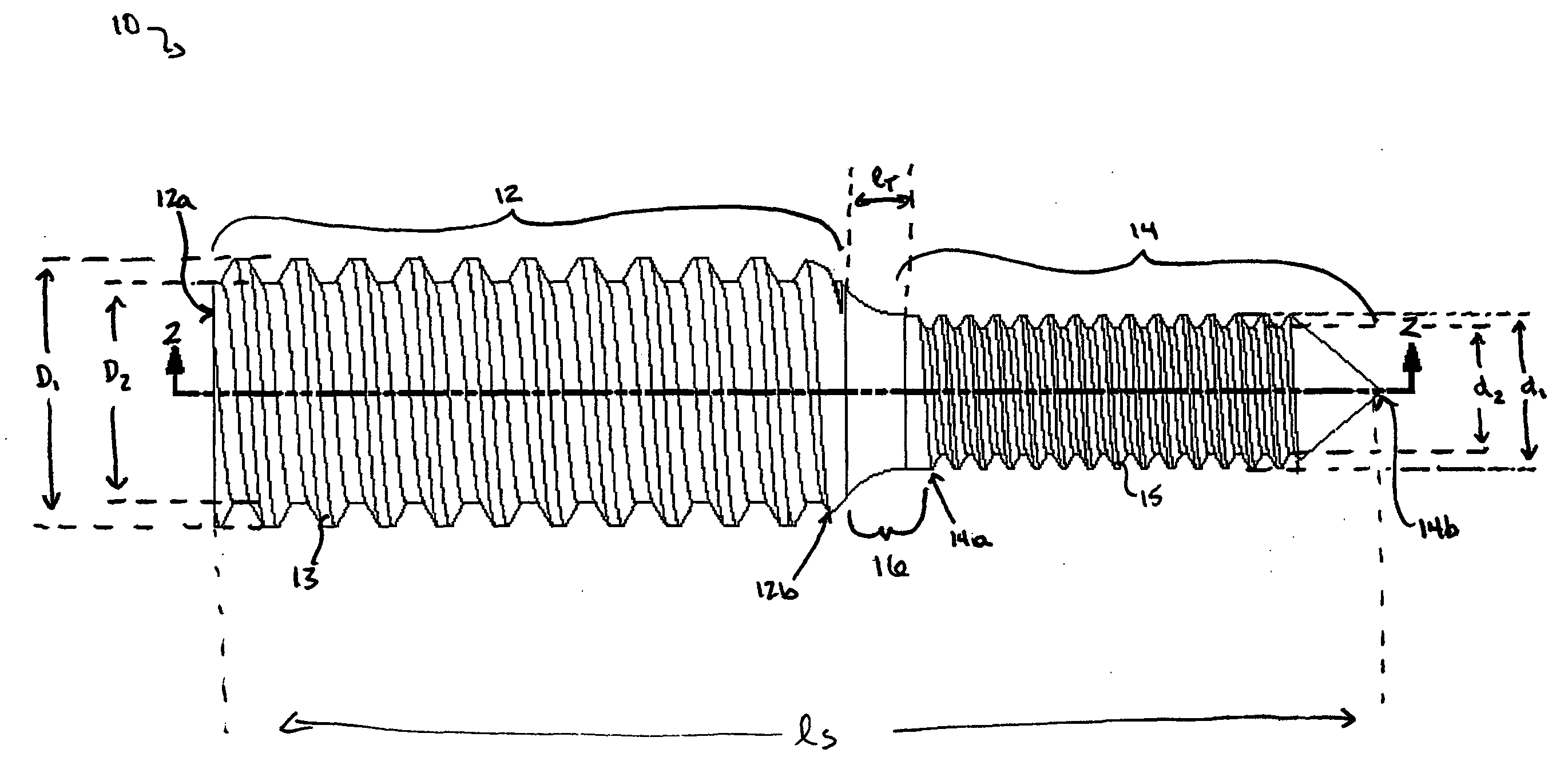
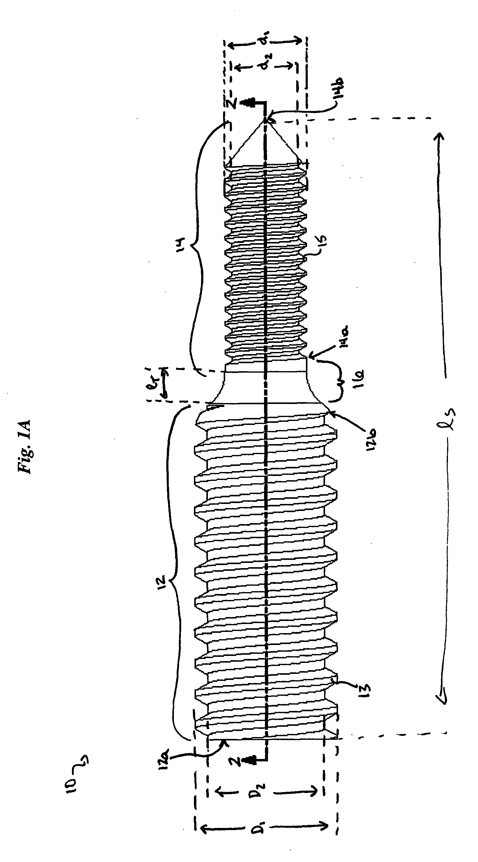
[0022] The present invention provides a bone screw for distracting two pieces of bone, and more preferably for expanding a spinal canal. In general, the bone screw includes a shank having a proximal and distal portions that are adapted to engage two segments of bone, and to create a distraction force between the two segments of bone. The bone screw is particularly advantageous in that it is easy to use, it maintains normal anatomic structures and muscle attachments, and it can be efficiently implanted, thereby reducing the time and expense necessary to perform spinal surgery.

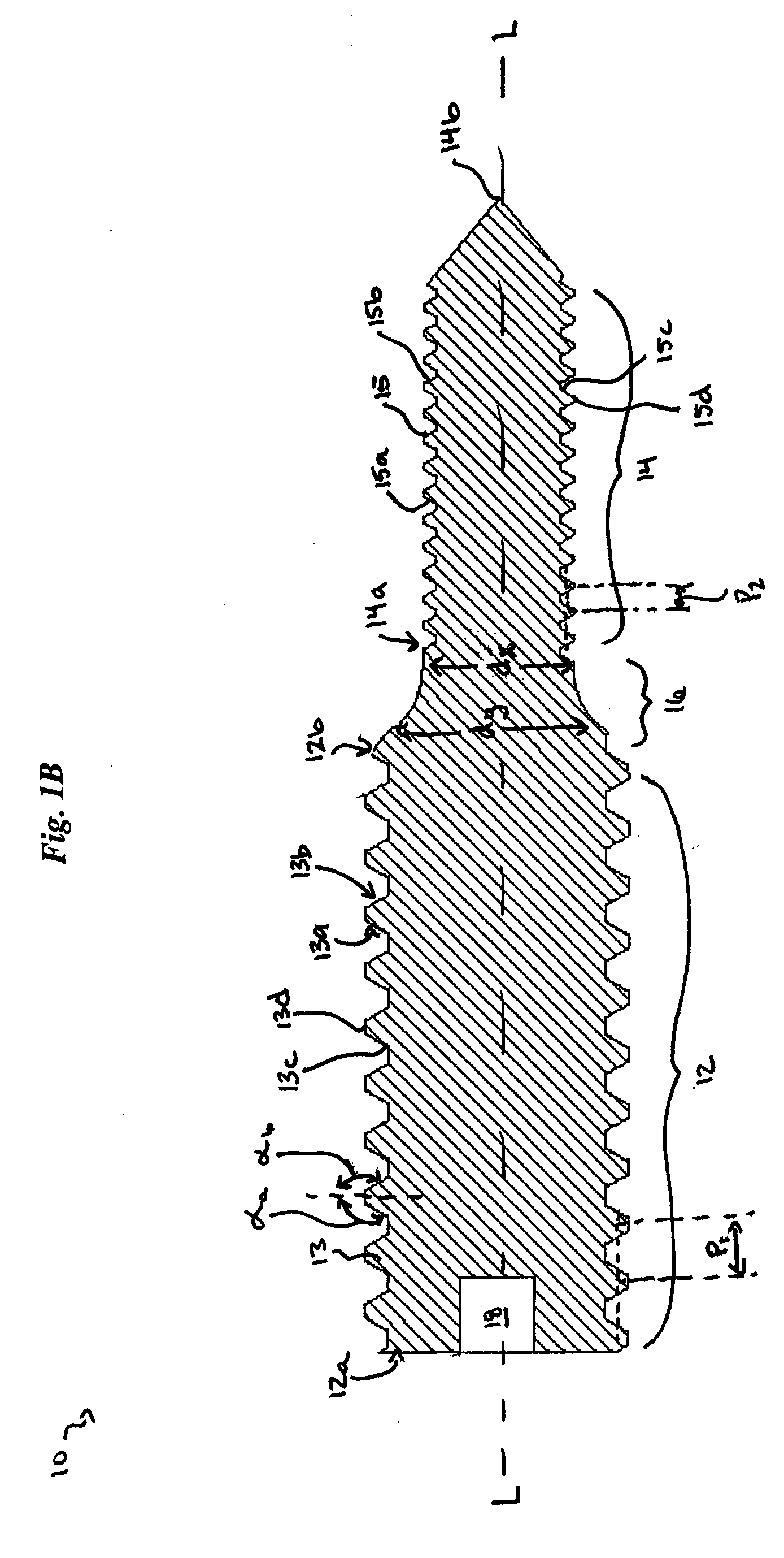
[0023]FIGS. 1A-1C illustrate one embodiment of a bone screw 10 in accordance with the present invention. As shown, the bone screw 10 includes a shank having a proximal portion 12 with at least one thread 13 formed thereon, a distal portion 14, and a transitional region 16, optionally of decreasing diameter, disposed between the threaded proximal portion 12 and the distal portion 14. The overall size of the bone...


PUM


Abstract

A simple, safe implantable bone screw, and a method for distracting two bone segments, is provided. In general, the bone screw includes a shank having a threaded proximal portion and a distal portion with a major diameter that is less than a minor diameter of the threaded proximal portion. A transitional region of decreasing diameter can be disposed between the threaded proximal portion and the distal portion, and a driver receiving element is preferably disposed on a proximal end of the bone screw. In use, the proximal and distal portions of the bone screw are adapted to engage two segments of bone, and to create a distraction force between the two segments of bone.

Description

FIELD OF THE INVENTION [0001] The present invention relates to a bone screw for distracting two segments of bone, and in particular to an implantable bone screw for use in spinal surgery to expand the spinal canal. BACKGROUND OF THE INVENTION [0002] U.S. Pat. No. 6,358,254 to Anderson, the disclosure of which is incorporated by reference, describes spinal stenosis as a condition that inflicts millions of people with back and leg pain due to compression of spinal nerves. Severe cases often require surgery to relieve nerve compression and lessen the back and leg pain. A spinal laminectomy is the traditional operation performed to treat spinal stenosis. In this operation, the posterior aspects of the spinal column are removed to “unroof” the spinal canal and relieve the pressure on the nerves. Specifically, the spinous processes, lamina and portions of the facet joints are excised to relieve the nerve root compression. [0003] Although a spinal laminectomy is often successful in relievi...

Claims


Application Information

Patent Timeline
IPC IPC(8): A61B17/00A61B17/70A61B17/86
CPCA61B17/7071A61B2017/00004A61B17/8635A61B17/863
Inventor ANDERSON, DAVID GREGMCCREA, CONORRAMSAY, CHRISTOPHER
Owner DEPUY ACROMED INC
Why Eureka
Try Eureka