

Device and a method for continuous casting
a continuous casting and metal technology, applied in casting apparatus, metal-working apparatus, manufacturing tools, etc., can solve problems such as large problems, inability to accurately measure the effect of casting,
- Summary
- Abstract
- Description
- Claims
- Application Information
AI Technical Summary
Benefits of technology
Problems solved by technology
Method used
Image

Examples
Embodiment Construction
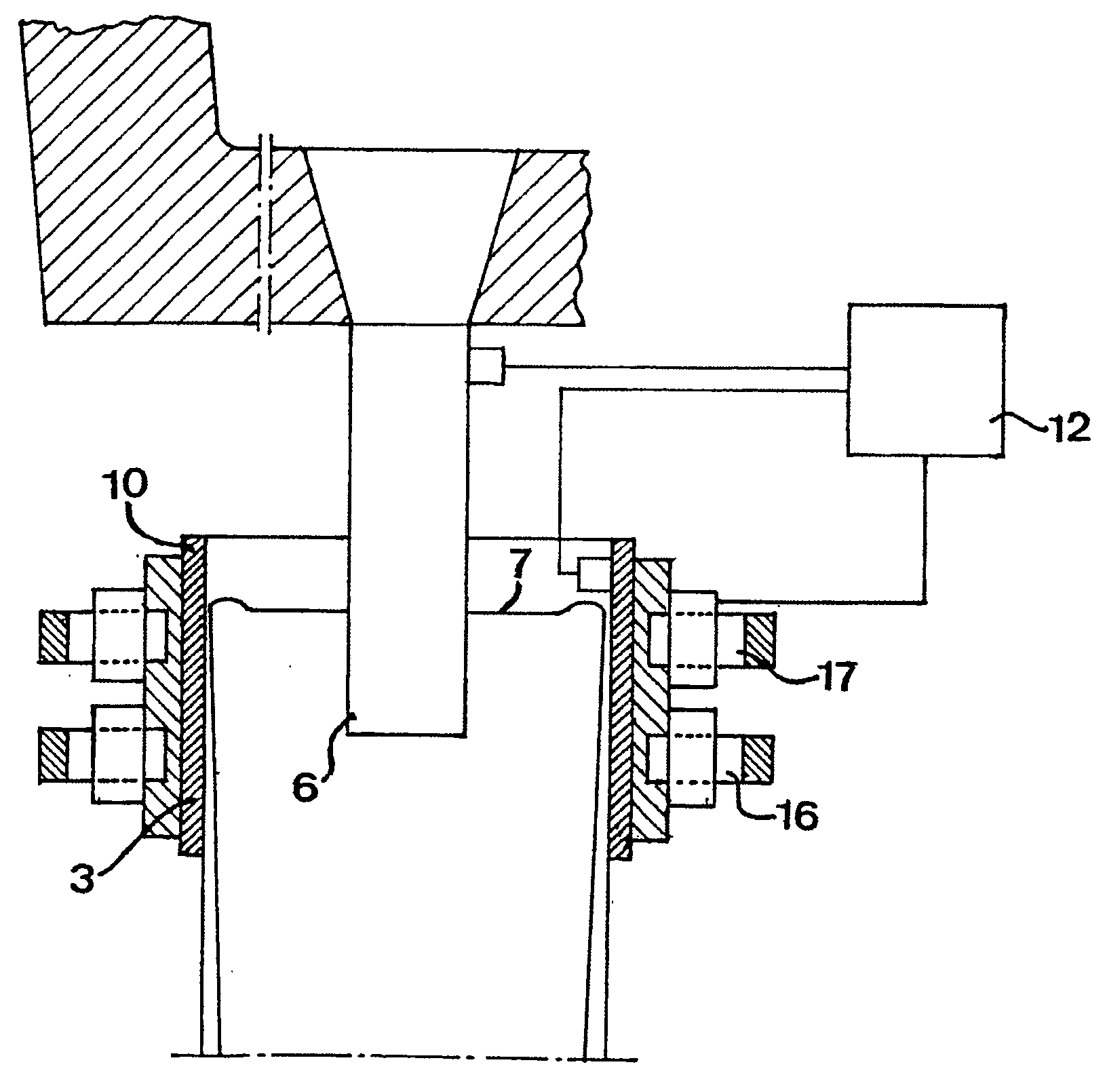
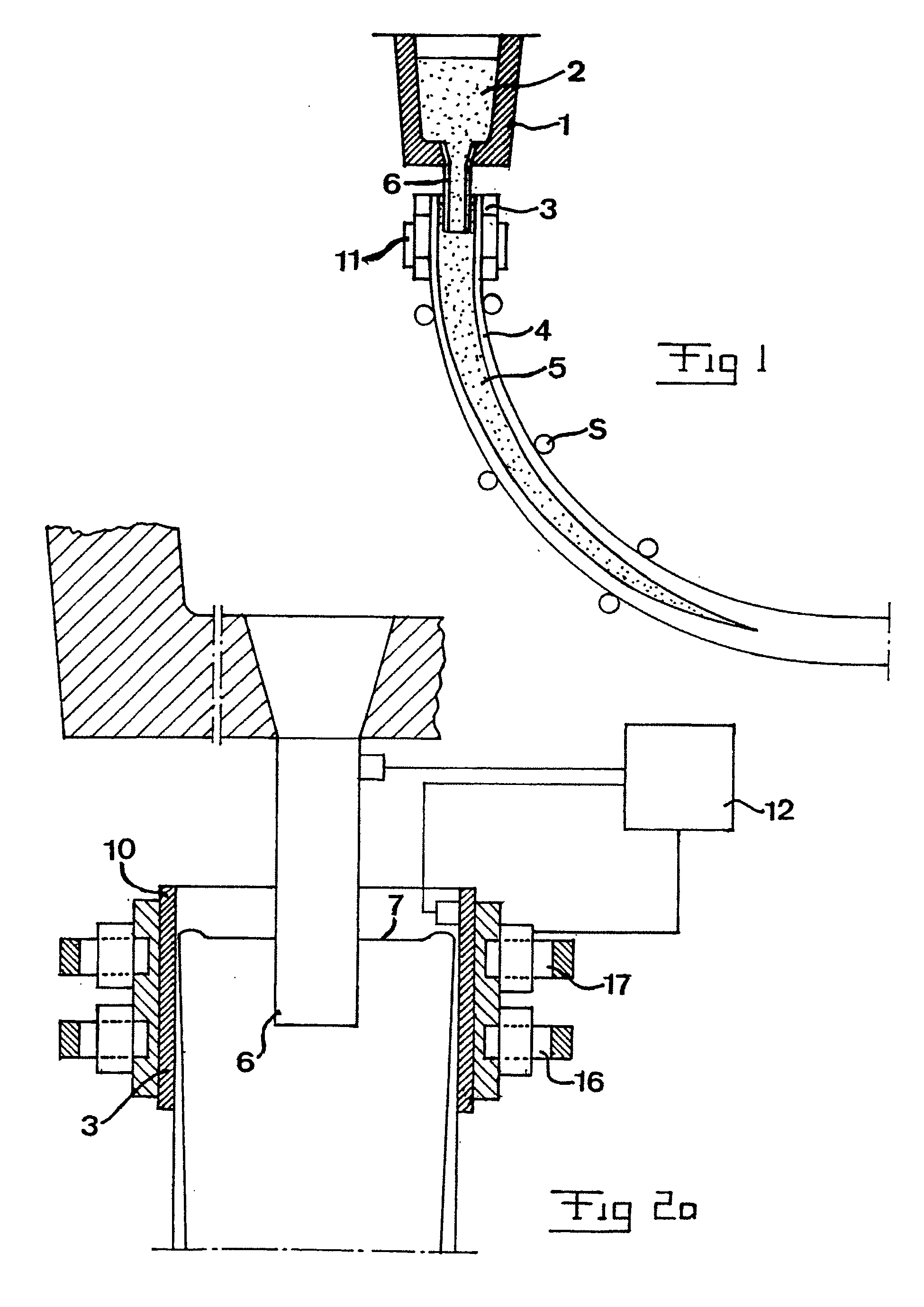
[0034] The principles of the invention will now be described with reference to FIGS. 2-4, which in a simplified manner illustrate an apparatus for continuous casting of metals according to a first preferred embodiment of the invention. As previously stated, the casting mould 3 has an elongated horizontal cross section, and in practice this normally means a considerably smaller relation of length of the short side to length of the long side than what is shown in the figures, and in this respect the figures are only to be interpreted as explaining the principles of the invention. Thus, the thickness of the strand may, for example, be of the order of magnitude of 150 mm while at the same time its width is over 1,500 mm.
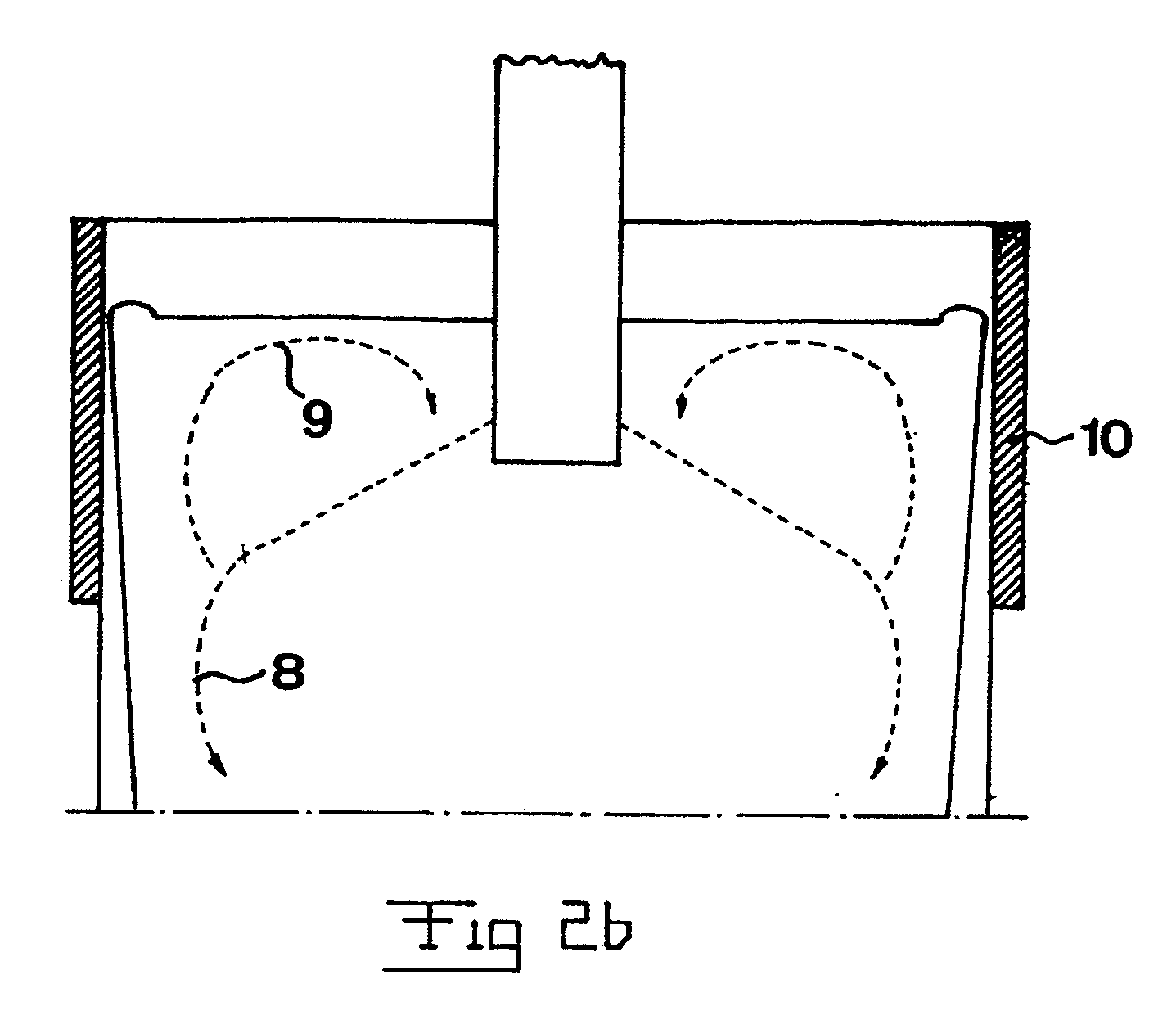
[0035] The molten metal that is supplied to the casting mould has a certain overtemperature, that is, the temperature thereof must be lowered to a certain extent in order for any part thereof to start solidifying. This is important in order to avoid that solidification ...
PUM
| Property | Measurement | Unit |
|---|---|---|
| Frequency | aaaaa | aaaaa |
| Temperature | aaaaa | aaaaa |
| Magnetic field | aaaaa | aaaaa |
Abstract
Description
Claims
Application Information