
Spout for pouch and plastic pouch with spout fixed thereto

a technology of spout and pouch, which is applied in the direction of sacks, packaging, flexible containers, etc., can solve the problems of contents leaking out of the pouch, the spout cannot be fixed to the pouch at the desired level of heat sealing strength, and the difficulty in heat sealing between the spout and the pouch, etc., to achieve constant thickness, improve the heat sealing ability, and maintain the effect of thickness

Inactive Publication Date: 2005-02-24
TOYO SEIKAN KAISHA LTD
View PDF6 Cites 49 Cited by
  • Summary
  • Abstract
  • Description
  • Claims
  • Application Information

AI Technical Summary

Benefits of technology

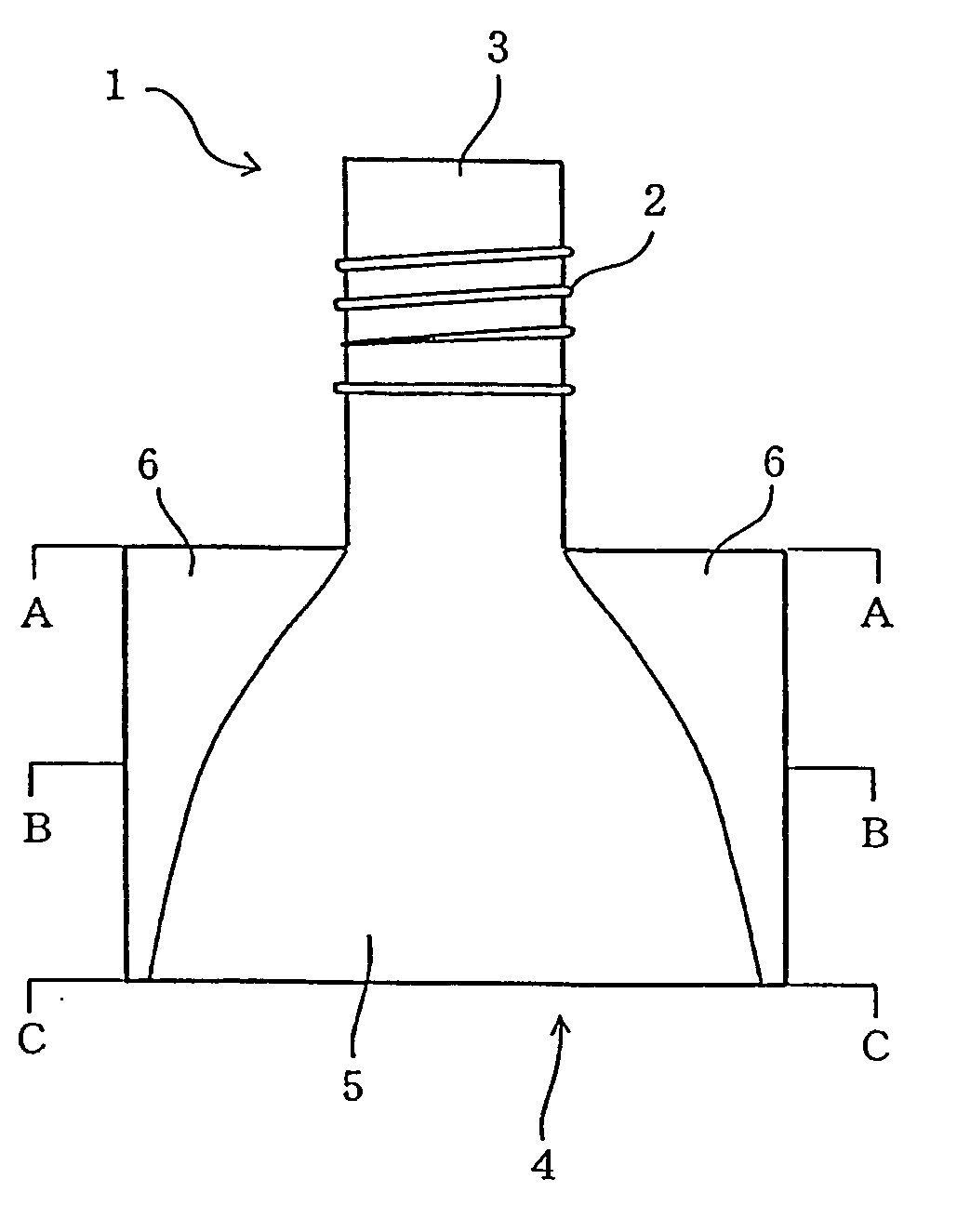
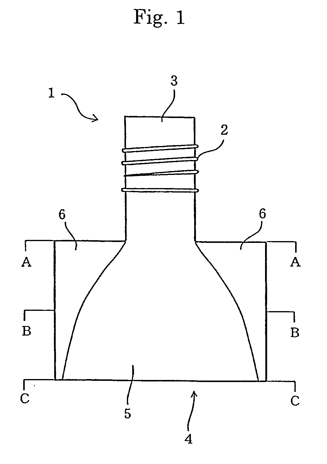
[0062] By setting the imaginary outer peripheral length of the spout 1 in such a manner, the heat-sealing capability between the spout 1 and the plastic pouch can be further improved. The spout 1 of this example can also provide similar advantageous effects to those obtainable with the spout shown in FIG. 1.
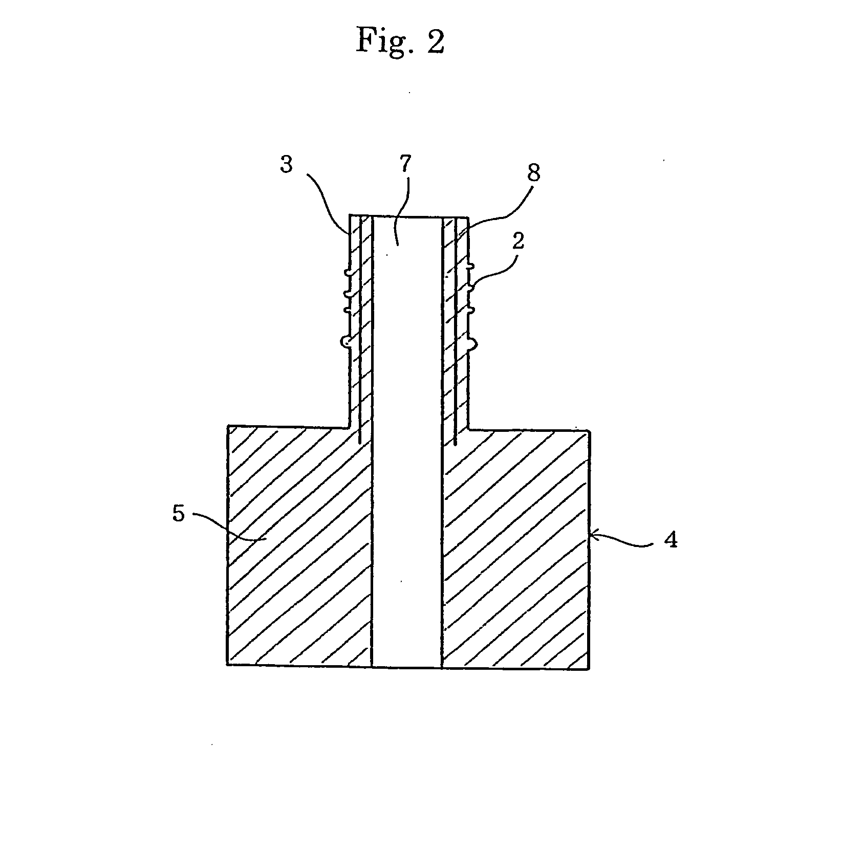
[0063]FIG. 12 shows still another example of the spout for the pouch according to the present invention. More specifically, FIG. 12(A) is a front view of the spout, and FIG. 12(B) is a vertical cross-sectional view taken along the line ZZ in FIG. 12(A). In the spout 1 of this example, the seal part 4 is constructed by providing a pair of flat wings 6, 6, each of which has a substantially constant thickness, on opposite lateral sides of a truncated cone-shaped barrel 5 having a substantially constant thickness. Further, hanger flanges 10, 10 each having a substantially rectangular plan shape are formed at a root of the mouth part 3 of the spout 1, and ribs 13 are provided on an outer periphery of the barrel 5 and on the wings 6 for improving the heat-sealing capability between the spout 1 and the pouch.
[0064] While, in the illustrated example, the ribs 13 are provided to extend in the horizontal direction parallel to each other, it is needless to say that the arrangement of the ribs 13 can be modified as required. For example, the ribs 13 may be provided to extend in the vertical direction.
[0065] Comparing with the conventional spout, shown in FIG. 17, in which the horizontal cross-sectional shape is the same at the upper end portion and the lower end portion, the spout for the pouch according to the present invention, shown in the examples described above, has the improved effect of preventing a phenomenon that the film constituting the pouch body is bent to cause a blockage at a position just below the spout when the contents are poured.
[0066] In the conventional spout for the pouch, it is also proposed to provide a bar-like member extending downward from the spout for preventing the occurrence of a blockage and ensuring a capability of pouring the contents. With the spout for the pouch according to the present invention, however, such a bar-like member can be omitted and hence an amount of raw material for producing the spout can be cut down. Without the bar-like member, the pouch can be folded into a smaller size correspondingly. This brings about such advantages as (1) the remaining amount of the contents can be reduced (i.e., a consumer can drink the contents up to the last), and (2) because the pouch can be folded into a smaller size when discarded after the use, the volume of pouches discarded in folded states can be reduced. As a matter of course, as shown in FIG. 13, to ensure a more reliable capability of pouring the contents, the bar-like member may be provided to extend downward from the spout.
[0067]FIG. 13 is a front view showing still another example of the spout according to the present invention.

Problems solved by technology

When fixing a cylindrical spout 21 to a mouth part of a plastic pouch 22 by heat sealing, however, wrinkles 23 are caused in a plastic film constituting a pouch body 22 in areas on the opposite lateral sides of the spout 21 inserted in the pouch (see FIG. 16), which causes much difficulty in performing the heat sealing between the spout and the pouch.
The spout cannot be fixed to the pouch at a desired level of heat-sealing strength.
Hence, in the event of the pouch with the spout being dropped, for example, in a state filled with the contents, the pouch may rupture in those areas and the contents may leak out of the pouch.
It is, however, very difficult to form the gas barrier layer having such a complicated shape in the spout.
Hence, that type of spout cannot be manufactured with practically feasible cost and processes.

Method used


Image

  • Spout for pouch and plastic pouch with spout fixed thereto
  • Spout for pouch and plastic pouch with spout fixed thereto
  • Spout for pouch and plastic pouch with spout fixed thereto

Examples


example 1

[0095] A spout having a shape shown in FIG. 12 was manufactured through compression molding of polypropylene. The spout was dimensioned such that the overall height was 45 mm, the height of a seal part was 17 mm, the width of a lower end of the seal part was 24 mm, an upper end of the seal part had a circular cross-section with a diameter of 11.2 mm, the thickness of the seal part was 1.4 mm, and the thickness of a fitting portion of the cylindrical mouth part to the cap was 1.0 mm.

[0096] A multilayered film made of 12 μm-thick polyethylene terephthalate / 15 μm-thick biaxially oriented nylon / 7 μm-thick aluminum alloy foil / 50 μm-thick polypropylene in this order from the outer layer side was used as an envelope material constituting a pouch body. The multilayered film was heat-sealed to the manufactured spout after arranging the spout, as shown in FIGS. 4 and 5, such that the upper end of the seal part of the spout was positioned inside an upper end of the pouch body. Thus, standing ...


PUM

PropertyMeasurementUnit
Lengthaaaaaaaaaa
Thicknessaaaaaaaaaa
Shapeaaaaaaaaaa

Abstract

The invention provides a spout for a pouch, which can be reliably heat-sealed with a plastic pouch body to provide an excellent gas-shielding capability for preventing gas permeation through the spout itself, and can be simply manufactured at a low cost without requiring complicated processes and special materials. In a spout for a pouch, comprising a tubular mouth part having a cap fitting portion and a seal part connected to a lower end portion of the mouth part for sealing with the pouch, the invention is featured in that a horizontal cross-sectional shape of the seal part is different in a height direction between an upper end portion and a lower end portion thereof, and an outer peripheral length of the horizontal cross-sectional shape is substantially equal at any position between the upper end portion and the lower end portion of the seal part.

Description

FIELD OF THE INVENTION [0001] The present invention relates to a spout for a pouch, which is fixed to a plastic pouch for containing beverages, foods, seasonings, pharmaceuticals, cosmetics, detergents, etc., and also related to a plastic pouch with the spout fixed thereto. BACKGROUND OF THE INVENTION [0002] A pouch with a spout, i.e., a pouch formed of a heat-sealed plastic film and having a spout fixed to the opening portion of the pouch, is widely used as means for containing beverages, foods, seasonings, pharmaceuticals, cosmetics, detergents, etc. [0003] As a spout of such a plastic pouch, there is known a cylindrical spout as shown in FIG. 16. When fixing a cylindrical spout 21 to a mouth part of a plastic pouch 22 by heat sealing, however, wrinkles 23 are caused in a plastic film constituting a pouch body 22 in areas on the opposite lateral sides of the spout 21 inserted in the pouch (see FIG. 16), which causes much difficulty in performing the heat sealing between the spout ...

Claims


Application Information

Patent Timeline
IPC IPC(8): B65D33/38B65D75/00B65D75/58
CPCB65D75/008B65D2575/583B65D75/5883B65D33/00
Inventor KUROSAWA, KAZUYUKIMATSUDA, NAOTOTAKEUCHI, KIMIOKUROSAWA, TAKAHIRO
Owner TOYO SEIKAN KAISHA LTD
Learn More